Spliced intravascular stent

A vascular stent and splicing technology, which is applied in the field of medical devices, can solve the problems of difficulty in adapting to different diseased areas of individual vascular anatomical structures of different patients, and poor versatility, so as to achieve the effect of reducing types and specifications and improving versatility

Pending Publication Date: 2021-08-24
胡佳
View PDF0 Cites 1 Cited by
  • Summary
  • Abstract
  • Description
  • Claims
  • Application Information

AI Technical Summary

Problems solved by technology

[0006] The purpose of the present invention is to provide a spliced ​​vascular stent, which is used to improve the shortcomings of the prior art that the...

Method used


Image

  • Spliced intravascular stent
  • Spliced intravascular stent
  • Spliced intravascular stent

Examples


Embodiment 1

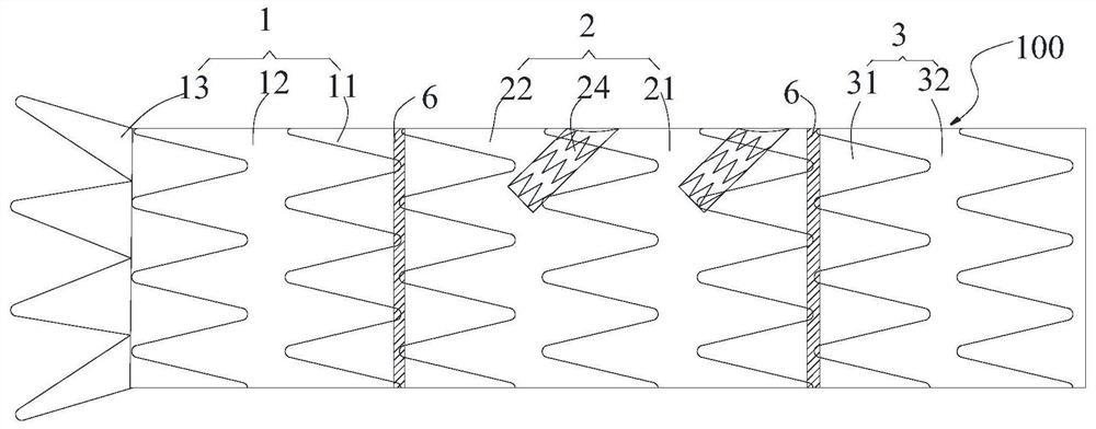
[0072] Such as Figure 9 As shown, the spliced ​​vascular stent 100 of the present application includes a first stent 1 , a second stent 2 , a third stent 3 and a fixing member 6 .

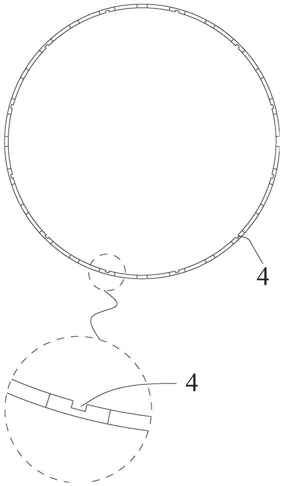
[0073] The first stent 1 includes a first main body tube 11 and a first film 12 covering the outer surface of the first main body tube 11. The second end of the first main body tube 11 is provided with a plurality of The limiting grooves are arranged, and each limiting groove extends along the circumferential direction of the first main body pipe 11 .

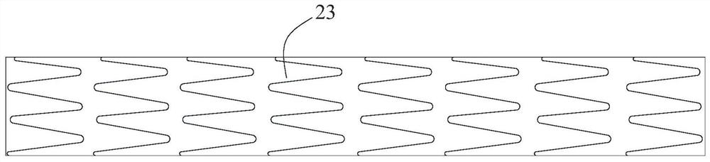
[0074] The second stent 2 includes a second main tube 21, a second coating 22, a branch tube 23 and an embedded tube 24. The second coating 22 covers the outer surface of the first main tube 11, and the embedded tube 24 is accommodated in the first main tube 11. Two inner chambers of the main body pipe 21, and one end of the embedded pipe 24 is connected with the pipe wall of the second main body pipe 21, and one end part of the branch pipe 23 is ...

Embodiment 2

[0079] Compared with Example 1, as Figure 10 As shown, the difference of this embodiment is that this embodiment only includes the first support 1, the third support 3 and the fixing member 6, and the first end of the first support 1 is provided with an anchor 13, by using the first support 1 A bracket 1 and a third bracket 3 are spliced ​​so that the first bracket 1 and the third bracket 3 are sequentially spliced ​​together, and are further fixed by the fixing member 6 at the joint where two adjacent brackets are spliced.

[0080] The spliced ​​vascular stent 100 can be implanted into the thoracic aorta to protect the diseased vessels of the thoracic aorta.

Embodiment 3

[0082] Compared with Example 1, as Figure 11 As shown, the difference of this embodiment is that this embodiment only includes a first bracket 1 and two second brackets 2, and the first end of the first bracket 1 is provided with an anchor 13, by using the first bracket 1 and two second brackets 2 are sequentially spliced ​​so that the first bracket 1 and the two second brackets 2 are sequentially spliced ​​into one body, and are further fixed by the fixing member 6 at the joint where two adjacent brackets are spliced.

[0083] The spliced ​​vascular stent 100 can be implanted into the thoracoabdominal aorta to protect the diseased vessels of the thoracoabdominal aorta.


PUM


Abstract

The invention discloses a spliced intravascular stent. The spliced intravascular stent comprises a first stent and a second stent, the first stent comprises a first body pipe, and a first connecting structure is arranged at the second end of the first body pipe. The second stent comprises a second main body pipe, and a second connecting structure is arranged at the first end of the second main body pipe; the first connecting structure and the second connecting structure are arranged in a matched mode so that the first support and the second support can be spliced into a whole. According to the technical scheme provided by the spliced intravascular stent, the first stent and the second stent can be selected to be matched and spliced according to the condition of a patient, and the spliced stent is implanted into a diseased region of the patient, so that disease treatment of the patient is realized. Therefore, the splicing type intravascular stent can adapt to blood vessel anatomical structures or different diseased regions of different patient individuals, the types and specifications of the stent are reduced, and the universality of the splicing type intravascular stent is improved.

Description

technical field [0001] The invention belongs to the technical field of medical devices, in particular to a spliced ​​blood vessel stent. Background technique [0002] The aorta is the largest arterial vessel in the human body, and all blood transport in the human body needs to pass through the aorta. Under the long-term impact of high-pressure blood flow, the aortic vessel is prone to rupture or lesion, and then forms aortic dissection or aortic aneurysm. Aortic dissection and aortic aneurysm have rapid onset and great damage to the patient's body, so they have become one of the most difficult diseases in the cardiovascular field. [0003] At present, there are many stent products on the market for the treatment of aortic dissection or aortic aneurysm. Although they can all be effective in treating aortic lesions in the corresponding parts, these stents have the following problems: [0004] The structure is relatively fixed, and it is difficult to adapt to the vascular ana...

Claims


Application Information

Patent Timeline
IPC IPC(8): A61F2/856A61F2/90
CPCA61F2/856A61F2/90A61F2002/821A61F2002/823
Inventor 胡佳
Owner 胡佳
Why Eureka
Try Eureka