
Milling cutter for wood processing

A milling cutter and wood technology, which is applied in the field of milling cutters for wood processing, can solve problems affecting processing quality, affecting cutter body grinding, air pollution, etc., and achieves the effects of easy and stable placement, reducing dust pollution, and improving quality

Active Publication Date: 2021-08-27
满洲里江诚木材贸易有限公司
View PDF6 Cites 1 Cited by
  • Summary
  • Abstract
  • Description
  • Claims
  • Application Information

AI Technical Summary

Problems solved by technology

[0006] 1. Although the above-mentioned device is easy to operate and has good stability, when the milling cutter is in use, especially when the cylindrical milling cutter is used to polish and carve the surface of the wood product, the waste chips of the wood product will be lost under the high-speed rotation of the milling cutter. Flying up will cause confusion on the table, and the dust generated will also rise with the high-speed rotation, causing air pollution and inconvenient collection. If a large amount of sawdust accumulates on the workbench, it will cause the wooden products to be placed unevenly and affect the processing quality ;
[0007] 2. When the cutter body is grinding the outer surface of wood products, although the cutter body can eject the sawdust at high speed, after the milling cutter runs for a period of time, there may be some flying chips between the motor and the cutter body, which will affect the speed. In addition, the fine ash mixed in the sawdust will remain between the fine-toothed knife on the outer surface of the knife. If it is not cleaned in time, it will affect the grinding of the knife body and also affect the maintenance of the knife body.

Method used


Image

  • Milling cutter for wood processing
  • Milling cutter for wood processing
  • Milling cutter for wood processing

Examples


Embodiment Construction

[0039] The following will clearly and completely describe the technical solutions in the embodiments of the present invention with reference to the accompanying drawings in the embodiments of the present invention. Obviously, the described embodiments are only some, not all, embodiments of the present invention. Based on the embodiments of the present invention, all other embodiments obtained by persons of ordinary skill in the art without making creative efforts belong to the protection scope of the present invention.

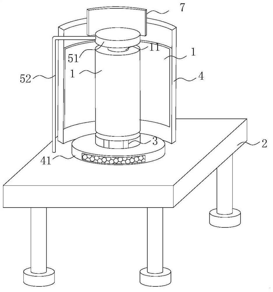
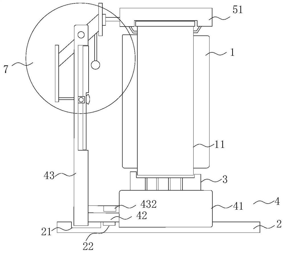
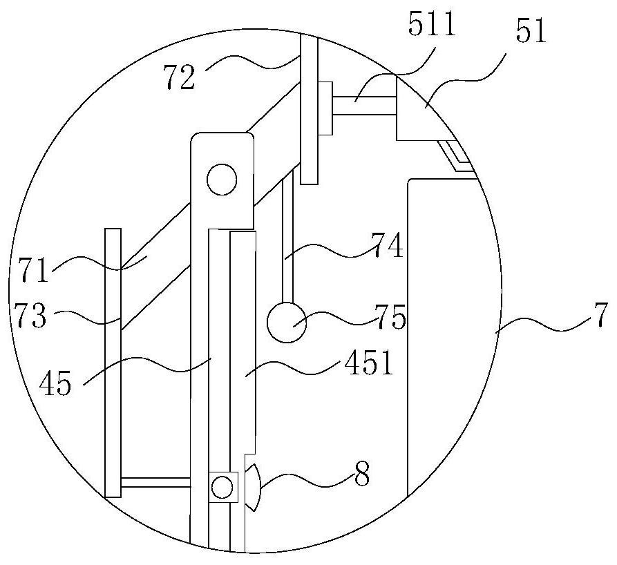
[0040] see Figure 1 to Figure 7 , the present invention provides a technical solution:

[0041] A milling cutter for wood processing, comprising a cutter body 1 and a workbench 2, the cutter body 1 is fixedly installed at the center of the upper end outer surface of the workbench 2, and the upper end outer surface of the workbench 2 is close to the left and right sides of the rear end The positions are all provided with chute 21, and the two chute 21 are lef...


PUM


Abstract

The invention relates to the technical field of milling cutters, in particular to a milling cutter for wood processing. The milling cutter comprises a cutter body and a workbench, the cutter body is fixedly installed in the center of the outer surface of the upper end of the workbench, the positions, close to the left side and the right side of the rear end, of the outer surface of the upper end of the workbench are provided with chutes, the two chutes are in bilateral symmetry, a first discharging opening is formed in the position, close to the rear end, of the outer surface of the upper end of the workbench, the cutter body is cylindrical, a rotating shaft penetrates through the interior of the cutter body, a motor is fixedly installed at the lower end of the rotating shaft, and a protection mechanism is arranged at the lower end of the motor; and the protection mechanism comprises an empty cylinder, a T-shaped push plate, an arc-shaped plate and a sliding assembly, the empty cylinder is fixedly installed on the outer surface of the lower end of the motor, and the lower end of the empty cylinder is embedded into the workbench. According to the milling cutter for wood processing, disorder and dust pollution of the workbench can be reduced, waste chips can be conveniently collected, the grinding quality is improved, smooth operation and rotation of the cutter body are ensured, the working efficiency is improved, and maintenance of the cutter body is enhanced.

Description

technical field [0001] The invention relates to the technical field of milling cutters, in particular to a milling cutter for wood processing. Background technique [0002] A milling cutter is a rotating tool with one or more teeth for milling. When working, each knife tooth cuts off the allowance of the workpiece intermittently in turn. Among them, cylindrical milling cutters are mainly used for machining planes, steps, grooves, forming surfaces and cutting workpieces on milling machines, and are used for machining planes on horizontal milling machines; [0003] Milling is an important and efficient processing method in wood cutting. It can be used not only to process planes and grooves, but also to process various molding surfaces and curved surfaces. With people's greater demand for wood furniture and higher requirements for processing efficiency, milling is increasingly used in wood product processing. [0004] Existing patent (notification number: CN207402180U), an e...

Claims


Application Information

Patent Timeline
Patent Type & Authority Applications(China)
IPC IPC(8): B27C5/02B27G3/00F16N11/10
CPCB27C5/02B27G3/00F16N11/10Y02P70/10
Inventor 陈维张可
Owner 满洲里江诚木材贸易有限公司
Learn More