An automated molding machine for making cement prefabricated components

A technology of prefabricated components and cement, applied in the direction of ceramic molding machines, ceramic molding cores, ceramic molding mandrels, etc., can solve the problems of heat generation, air holes, easy damage to the bottom surface of plate-shaped cement prefabricated components, etc., and achieve the goal of improving the molding quality Effect

Active Publication Date: 2022-06-21
CHUZHOU UNIV
View PDF13 Cites 0 Cited by
  • Summary
  • Abstract
  • Description
  • Claims
  • Application Information

AI Technical Summary

Problems solved by technology

[0005] The present invention provides an automatic molding machine for the production of cement prefabricated components, and aims to solve the following problems in the production process of plate-shaped cement prefabricated components: (1) heat will be generated during the cement solidification process, and the heat generated near the outer wall of the inner mold tube The heat generated by the cement cannot be discharged smoothly, resulting in air holes on the outer wall of the inner mold tube, which affects the molding quality of the plate-shaped cement prefabricated components; There will be a part of material shortage area under the mold tube, which will also adversely affect the forming quality of the plate-shaped cement precast component; (3) During the solidification process of the plate-shaped cement precast component, strong condensation occurs between the bottom surface and the bottom formwork In the process of separating the plate-shaped cement precast components from the bottom formwork, the bottom surface of the plate-shaped cement precast components is easily damaged, which will adversely affect the forming quality of the plate-shaped cement precast components

Method used


Image

  • An automated molding machine for making cement prefabricated components
  • An automated molding machine for making cement prefabricated components
  • An automated molding machine for making cement prefabricated components

Examples


Embodiment Construction

[0036] Embodiments of the present invention are described in detail below with reference to the accompanying drawings, but the present invention can be implemented in many different ways as defined and covered by the claims.

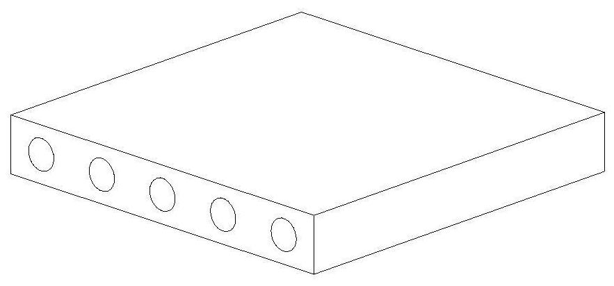
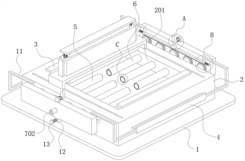
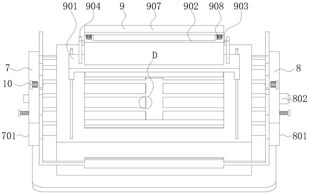
[0037] like Figure 2 to Figure 8 As shown, this embodiment provides an automatic molding machine for making cement prefabricated components, which is aimed at such as figure 1 The shown cement prefabricated component is manufactured, including a horizontal bottom plate 1, a mold box 2 is fixedly installed on the upper surface of the bottom plate 1, and a square groove 201 is vertically opened on the top surface of the mold box 2. The front and rear side walls of the square groove 201 are vertically slidably fitted with a side template 3, and the front and rear side walls of the mold box 2 are horizontally slidably fitted with a bottom template 4 that penetrates the mold box 2. The bottom surface of the bottom template 4 is connected to the square groove...


PUM


Abstract

The invention belongs to the technical field of cement products, and in particular relates to an automatic molding machine for making cement prefabricated components, which includes a bottom plate, a mold box is installed on the bottom plate, a square groove is opened on the top surface of the mold box, and a side formwork and a bottom are slidingly fitted on the inner wall of the square groove. Template; the first inner mold tube and the second inner mold tube are slidingly installed on the side wall of the mold box; the ends of the first inner mold tube are connected together through the first water changing mechanism, and the second inner mold tube is located at the end through the The two water-changing mechanisms are connected together; the top surface of the mold box is slidingly fitted with a leveling mechanism. During the production process of the plate-shaped cement prefabricated component, the invention avoids the occurrence of heat accumulation on the outer wall of the inner mold tube causing pores in the cement, avoids the occurrence of a material shortage area under the inner mold tube, and avoids the occurrence of the plate-shaped cement prefabricated component. Damage to the bottom surface of the plate-shaped cement prefabricated component occurs during the separation process from the bottom formwork.

Description

technical field [0001] The invention belongs to the technical field of cement products, in particular to an automatic molding machine for making cement prefabricated components. Background technique [0002] Cement prefabricated components refer to cement products processed and produced by standardized and mechanized methods in factories. Compared with cast-in-place cement, the quality and process of prefabricated cement components can be better controlled through mechanized production; the molds in the factory can be reused and the overall cost is lower; the standardization of prefabricated components and their properties can significantly speed up installation Due to the above advantages, cement prefabricated components are widely used in construction, transportation, water conservancy and other fields. [0003] There are many shapes of cement prefabricated components, the common ones include plate, cylinder and block. Among them, the plate-shaped cement prefabricated co...

Claims


Application Information

Patent Timeline
Patent Type & Authority Patents(China)
IPC IPC(8): B28B7/30B28B13/02B28B13/06B28B17/00
CPCB28B7/30B28B13/02B28B13/06B28B17/00
Inventor 王亚斌
Owner CHUZHOU UNIV
Why Eureka
Try Eureka