Debris flow pile group protection structure and system based on energy conversion enhancement mechanism

A technology of strengthening mechanism and energy conversion, which is applied in the direction of infrastructure engineering, protective equipment, sheet pile walls, etc., can solve the problems of affecting the blocking effect, the design height of single pile is small, and the risk of single pile damage is large, so as to achieve good protection effect, The effect of enhancing the protective effect

Active Publication Date: 2021-08-27
TONGJI UNIV
View PDF5 Cites 2 Cited by
  • Summary
  • Abstract
  • Description
  • Claims
  • Application Information

AI Technical Summary

Problems solved by technology

[0005] However, the existing pile group system has the following defects: (1) The pile group mainly dissipates its kinetic energy by enhancing the internal interaction of the debris flow, and the energy absorbed by the pile group structure itself is almost negligible. It is difficult to fundamentally improve the effect; (2) At present, the pile group is relatively effective in blocking debris flow, but it is not effective in blocking debris flow with high water content that lacks an effective energy dissipation mechanism; (3) Debris flow impact The effect is large, resulting in a greater risk of damage to the single pile, so the design height of the single pile is usually small, and the blocking effect is often affected by the overflow of debris flow

Method used


Image

  • Debris flow pile group protection structure and system based on energy conversion enhancement mechanism
  • Debris flow pile group protection structure and system based on energy conversion enhancement mechanism
  • Debris flow pile group protection structure and system based on energy conversion enhancement mechanism

Examples


Embodiment 1

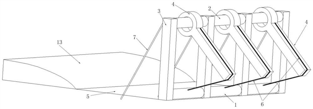
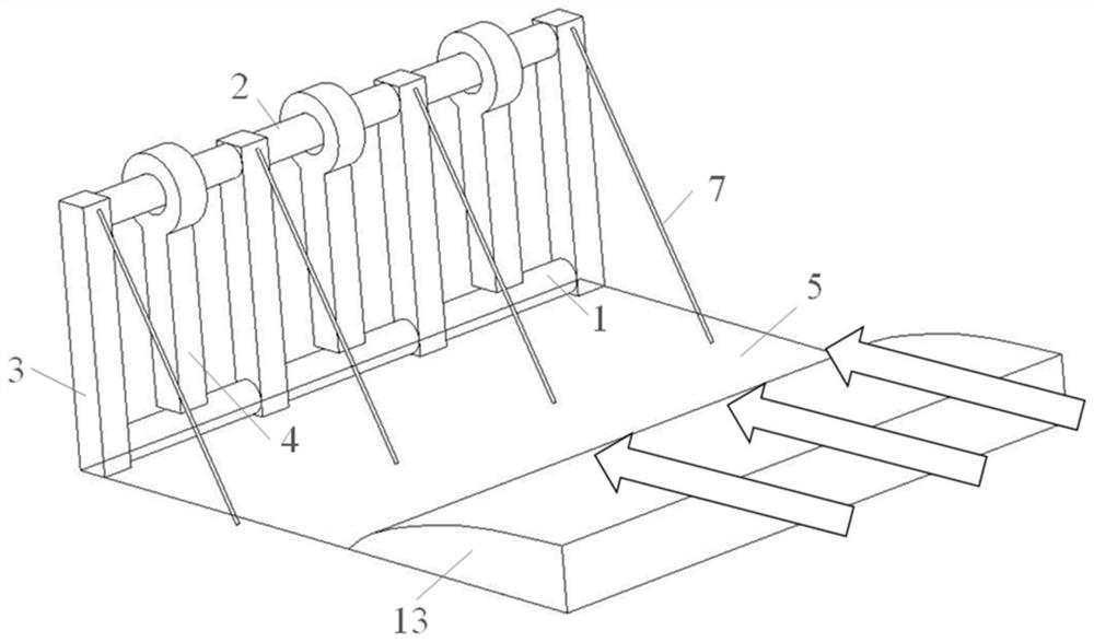
[0032] A protective structure of debris flow pile groups based on energy conversion enhancement mechanism, used to block debris flow13, such as figure 1 and figure 2 As shown, including ground beam 1, suspension beam 2, fixed pile 3 and rotating pile 4, ground beam 1 is installed on the ground 5, suspension beam 2 is parallel to ground beam 1, fixed pile 3 is perpendicular to suspension beam 2 and ground beam 1, fixed pile The two ends of 3 are fixedly connected with the suspension beam 2 and the ground beam 1 respectively, the upper end of the rotary pile 4 is rotatably connected with the suspension beam 2, and the rotary pile 4 and the ground beam 1 are connected by an energy-dissipating anchor cable structure 6 .

[0033] On the one hand, the top of the fixed pile 3 is fixedly connected with the suspension beam 2, and the top of the fixed pile 3 is provided with an anchor 7, and the other end of the anchor 7 is connected to the ground 5 for anchoring, and the anchor 7 is a...


PUM


Abstract

The invention relates to a debris flow pile group protection structure and system based on an energy conversion enhancement mechanism. The debris flow pile group protection structure comprises a ground beam, a cantilever beam, a fixed pile and a rotating pile, the ground beam is installed on the ground, the cantilever beam is parallel to the ground beam, the fixed pile is perpendicular to the cantilever beam and the ground beam, and the two ends of the fixed pile are fixedly connected with the cantilever beam and the ground beam correspondingly; and the upper end of the rotating pile is rotationally connected with the cantilever beam, and the rotating pile is connected with the ground beam through an energy dissipation anchor cable structure. Compared with the prior art, on the basis that the advantages of an original pile group structure are reserved, dissipation of debris flow impact energy by the pile group structure is further improved, the energy of debris flow is further absorbed or converted through the pile group structure besides energy dissipation through internal interaction inside the debris flow, therefore the debris flow pile group protection structure is suitable for prevention and treatment of the debris flow with different water contents, and the protection effect is good.

Description

technical field [0001] The invention relates to the field of disaster prevention and mitigation of geological disasters, in particular to a protection structure and system for debris flow pile groups based on an energy conversion enhancement mechanism. Background technique [0002] Debris flow refers to landslides or torrents caused by heavy rain, snowstorm, earthquake or other natural disasters, and carries a large amount of solid debris such as sand and stones. This kind of natural disaster mostly occurs in narrow valleys and areas with steep terrain. It has the characteristics of suddenness, fast flow rate, short duration, large flow rate, large amount of solid matter, and strong destructive power. It often causes great property losses and casualties. [0003] my country is a country with frequent debris flow disasters and extremely serious losses, especially in strong earthquake areas, strong earthquake disturbances, excessive and unreasonable post-earthquake reconstruct...

Claims


Application Information

Patent Timeline
Patent Type & Authority Applications(China)
IPC IPC(8): E02D5/22E02D5/74E01F7/04
CPCE02D5/226E02D5/74E01F7/045
Inventor 张贝黄雨
Owner TONGJI UNIV
Why Eureka
Try Eureka