
Transient modeling method for hydrogen circulating pump in fuel cell system

A technology of fuel cell system and modeling method, which is applied in the field of transient modeling of hydrogen circulation pumps, can solve problems affecting the cold start speed of fuel cells, increase the cost of use, damage performance of battery stacks, etc., and achieve important scientific significance and economic value , reduce the test bench test cost, and ensure the effect of simulation accuracy

Active Publication Date: 2021-08-27
TIANJIN UNIV
View PDF4 Cites 5 Cited by
  • Summary
  • Abstract
  • Description
  • Claims
  • Application Information

AI Technical Summary

Problems solved by technology

If the amount of hydrogen provided by the vehicle fuel cell is reduced or even in short supply, it will cause irreversible damage and performance degradation to the battery stack
Therefore, a certain amount of hydrogen must be guaranteed to maintain the operation of the battery stack, but if the hydrogen recovery subsystem is not installed, the unreacted hydrogen will be directly discharged into the environment
The waste of fuel will not only increase the cost of use and reduce the cruising range, but the key point is that there will be safety problems
In addition, in order to obtain better performance, the hydrogen at the anode inlet of the battery stack often needs to be humidified, and the humidifier will increase the volume and cost of the system, and the residual liquid water in the humidifier will freeze below zero, affecting the cold start of the fuel cell speed

Method used


Image

  • Transient modeling method for hydrogen circulating pump in fuel cell system
  • Transient modeling method for hydrogen circulating pump in fuel cell system
  • Transient modeling method for hydrogen circulating pump in fuel cell system

Examples


Embodiment Construction

[0052] The modeling process of the present invention will be further described through specific examples below. It should be noted that this calculation example is descriptive rather than restrictive, and does not limit the scope of protection of the present invention.

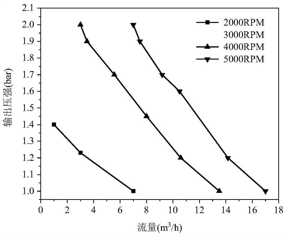
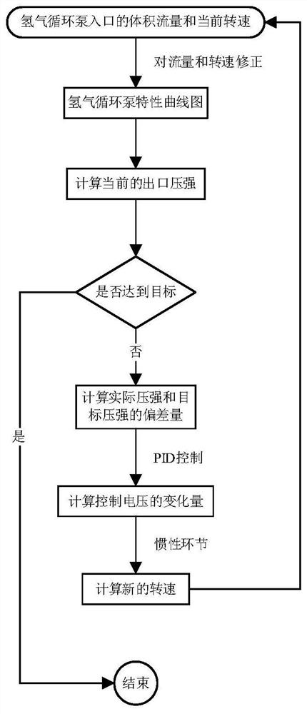
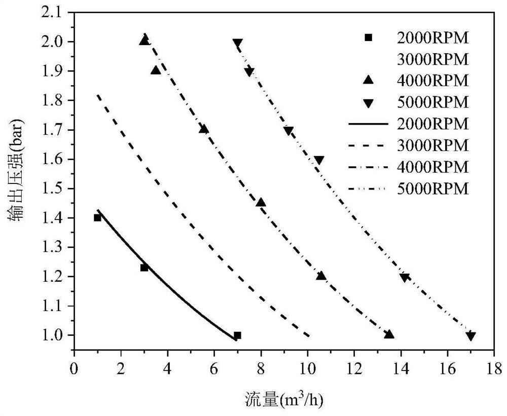
[0053] In the transient modeling method of the hydrogen circulation pump in the fuel cell system, firstly, the volume flow rate of the hydrogen circulation pump inlet and the current speed are corrected, and the current outlet pressure is obtained with the characteristic curve of the hydrogen circulation pump, and compared with the target outlet pressure, The difference between the two is used as the deviation of the PID control, so as to calculate the change of the control voltage, and then according to the inertial link model, a new speed is obtained, and finally combined with the inlet volume flow to recalculate, so that the actual outlet pressure Gradually approach or even equal to the target outlet pressur...


PUM


Abstract

The invention discloses a transient modeling method for a hydrogen circulating pump in a fuel cell system, and the method comprises the steps: carrying out the fitting of a model based on a polynomial regression method, obtaining a relation function of the flow, rotating speed and outlet pressure of the hydrogen circulating pump, coupling an inertia link of a drive motor, and constructing a complete transient centrifugal hydrogen circulating pump model; and finally, performing PID control on the control voltage of the driving motor, obtaining the transient response of the hydrogen circulating pump through coupling calculation of the three models, controlling the hydrogen circulating pump to meet the tail gas recycling requirement of the fuel cell stack, and therefore, the purpose of controlling the hydrogen circulating pump is achieved. The model obviously improves the calculation rate on the premise of ensuring the simulation accuracy, can be used for calculating the working condition of the fuel cell stack in a steady state, can also simulate and calculate the real-time transient response during the variable load of the electric pile under the actual road working condition, can better carry out linkage simulation with the fuel cell system, and the method has important significance for optimizing the control strategy of the fuel cell system.

Description

technical field [0001] The invention belongs to the field of fuel cells, and in particular relates to a transient modeling method for a hydrogen circulation pump in a proton exchange membrane fuel cell. Background technique [0002] In recent decades, the negative impact of air quality has been an urgent international problem, of which motor vehicle exhaust pollution accounts for a large proportion. In order to improve the air quality of cities, proton exchange membrane fuel cells have attracted the attention of many countries. It has become an important direction for the development of new energy vehicles. [0003] The fuel used by fuel cell vehicles comes from hydrogen stored in high-pressure hydrogen tanks. If the amount of hydrogen provided by the vehicle fuel cell is reduced, or even in short supply, it will cause irreversible damage and performance degradation to the battery stack. Therefore, a certain amount of hydrogen must be guaranteed to maintain the operation ...

Claims


Application Information

Patent Timeline
Patent Type & Authority Applications(China)
IPC IPC(8): H01M8/04298
CPCH01M8/04305Y02E60/50
Inventor 焦魁杨子俊杨子荣王博文
Owner TIANJIN UNIV
Learn More