
CFD software based method for optimizing temperature distribution of power battery pack

A power battery pack, temperature distribution technology, applied in the direction of electrical digital data processing, special data processing applications, instruments, etc., can solve the problems of slow same temperature process, damage battery cell life, damage battery cells, etc., to improve performance , Reduce the development cycle and reduce the cost of development

Inactive Publication Date: 2016-05-25
BRILLIANCE AUTO
View PDF5 Cites 13 Cited by
  • Summary
  • Abstract
  • Description
  • Claims
  • Application Information

AI Technical Summary

Problems solved by technology

When the prototype of the power battery system is not manufactured, the control strategy compiler cannot predict the defects and errors of the thermal management control strategy, so the debugging and optimization of the battery pack thermal management control strategy can only be placed after the sample package is produced, increasing The development cycle of the power battery system is shortened, and the time to market of the model is delayed
There are two disadvantages in debugging the control strategy on the power battery sample: On the one hand, due to the defect of the control strategy, the temperature distribution in the battery system is easy to be uneven during the debugging process, thereby damaging the life of the battery cell or even destroying the battery cell. Increased development costs; on the other hand, the control strategy needs to be debugged at different temperatures, which requires the power battery system to be at the same temperature in an incubator, and the same temperature process is very slow, increasing the development labor cost

Method used


Image

  • CFD software based method for optimizing temperature distribution of power battery pack

Examples


Embodiment 1

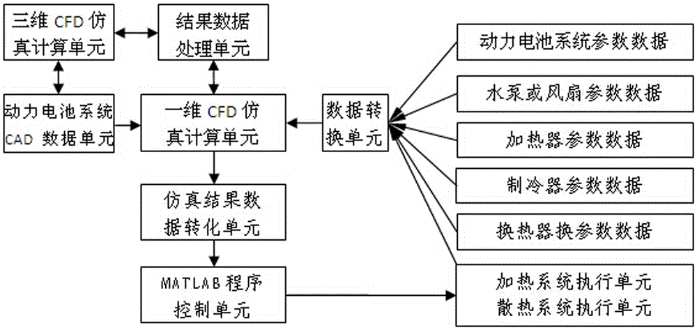
[0020] Depend on figure 1 As shown, this example includes a parameter data unit and a power battery system CAD data unit; the parameter data unit is connected to the input end of the one-dimensional CFD simulation calculation unit through a data conversion unit; the power battery system CAD data unit is connected to the one-dimensional CFD simulation calculation unit respectively The calculation unit is connected with the three-dimensional CFD simulation calculation unit, and the three-dimensional CFD simulation calculation unit is connected with the one-dimensional CFD simulation calculation unit through the result data processing unit; the output end of the one-dimensional CFD simulation calculation unit is sequentially passed through the result data processing unit and the MATLAB program The control unit is connected with the execution unit of the heating system and the heat dissipation system; the output end of the execution unit of the heating system and the heat dissipati...


PUM


Abstract

The invention discloses a CFD software based method for optimizing temperature distribution of a power battery pack. The method comprises a parameter data unit. The method has the technical key point that the parameter data unit is connected with the input end of a one-dimensional CFD simulation calculation unit through a data conversion unit; a CAD data unit of a power battery system is connected with the one-dimensional CFD simulation calculation unit and a three-dimensional CFD simulation calculation unit, and the three-dimensional CFD simulation calculation unit is connected with the one-dimensional CFD simulation calculation unit through a result data processing unit; the output end of the one-dimensional CFD simulation calculation unit is connected with a heating system and heat dissipation system execution unit through the result data processing unit and a MATLAB program control unit in sequence; and the output end of the heating system and heat dissipation system execution unit is connected with the input end of the one-dimensional CFD simulation calculation unit. According to the method, combined simulation calculation is realized through coupled calculation of one-dimensional fluid heat simulation and MATLAB, so that the simulation efficiency is improved and virtual hardware in-loop simulation is realized.

Description

technical field [0001] The invention relates to the technical field of power batteries of pure electric vehicles and hybrid vehicles, in particular to a method for optimizing the temperature distribution of power battery packs based on CFD software. In the present invention, the virtual physical model of the power battery pack established by the fluid simulation software and the control model established by MATLAB are used for coupling simulation, and the direct exchange of intermediate parameters is realized. Through the in-loop simulation of the virtual hardware, the control strategy can be quickly optimized and the thermal management can be fed back in time. Hardware structural design flaws. Background technique [0002] With the development and progress of society, the number of automobiles has increased rapidly, which has exacerbated the consumption of non-renewable resources. At the same time, automobile exhaust has also caused huge pollution, such as the increasingly ...

Claims


Application Information

Patent Timeline
Patent Type & Authority Applications(China)
IPC IPC(8): G06F17/50
CPCG06F30/367G06F2119/08
Inventor 王成瑞潘成久郭宏飞邢畅田旭董一鸣刘开平
Owner BRILLIANCE AUTO
Learn More