Constant-speed transfer structure of stamping parts based on intelligent manufacturing of auto parts

A technology of intelligent manufacturing and stamping parts, which is applied in the field of auto parts manufacturing, can solve the problems of inconvenient and fast installation of workpieces, high control costs, and lack of fast automatic transfer, so as to achieve the effect of automatic transfer and save control costs

Active Publication Date: 2021-10-01
NANTONG SUHE LAMP PARTS
View PDF9 Cites 0 Cited by
  • Summary
  • Abstract
  • Description
  • Claims
  • Application Information

AI Technical Summary

Problems solved by technology

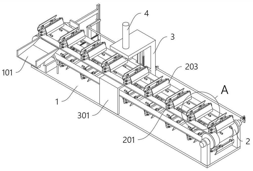
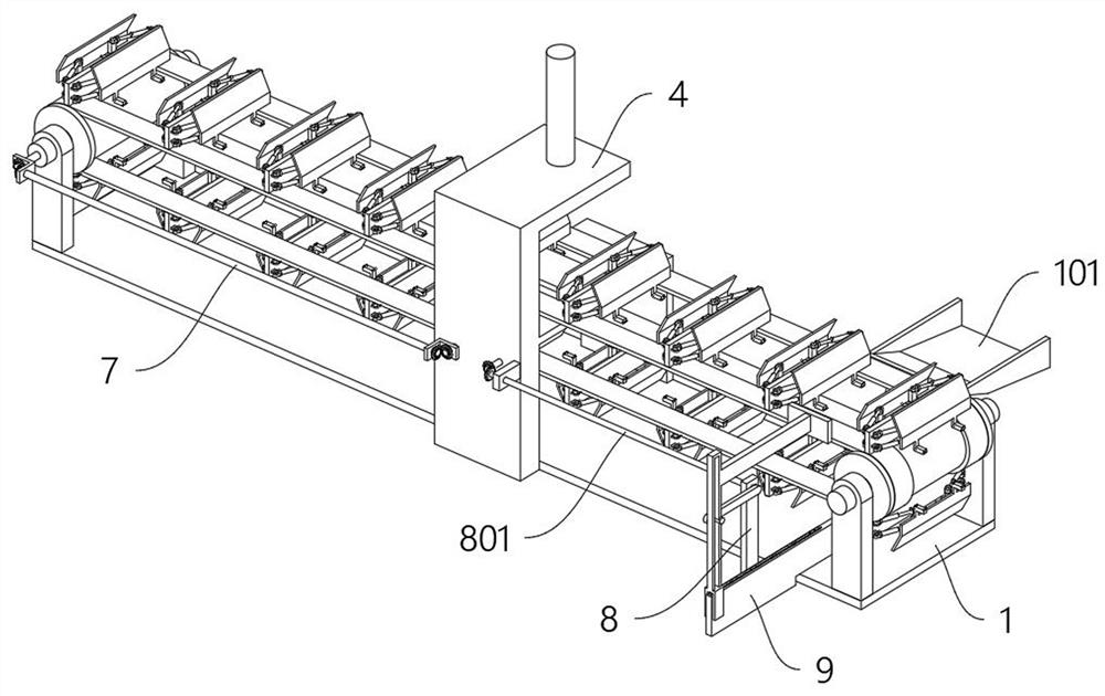
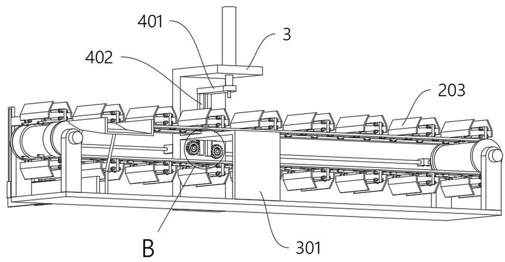
[0009] The purpose of the present invention is to provide a constant-speed transfer structure based on the intelligent manufacturing of stamping parts for auto parts, so as to solve the first problem proposed in the above-mentioned background technology. The currently used transfer structure is mainly controlled by a motor, and cannot be passed through a mechanical structure according to the steps of stamping. Realize the automatic control effect, the control cost is high, and there are hidden dangers of control failure; second, it does not have a convenient and flexible assembly structure, it is inconvenient to quickly install the workpiece, and ensure that the movement of the workpiece will not be hindered; third, it does not have fast automatic With the function of turning out, the stamped workpiece cannot be transported to another conveyor belt for subsequent processing while maintaining a horizontal state

Method used


Image

  • Constant-speed transfer structure of stamping parts based on intelligent manufacturing of auto parts
  • Constant-speed transfer structure of stamping parts based on intelligent manufacturing of auto parts
  • Constant-speed transfer structure of stamping parts based on intelligent manufacturing of auto parts

Examples


Embodiment Construction

[0051] The following will clearly and completely describe the technical solutions in the embodiments of the present invention with reference to the accompanying drawings in the embodiments of the present invention. Obviously, the described embodiments are only some, not all, embodiments of the present invention.

[0052] In the description of the present invention, unless otherwise stated, the meaning of "plurality" is two or more; the terms "upper", "lower", "left", "right", "inner", "outer" , "front end", "rear end", "head", "tail", etc. indicate the orientation or positional relationship based on the orientation or positional relationship shown in the drawings, and are only for the convenience of describing the present invention and simplifying the description, rather than Nothing indicating or implying that a referenced device or element must have a particular orientation, be constructed, and operate in a particular orientation should therefore not be construed as limiting ...


PUM


Abstract

The invention discloses a fixed-speed transfer structure based on the intelligent manufacturing of stamping parts of auto parts, relates to the technical field of auto parts manufacturing, and solves the problem that the currently used transfer structure is mainly controlled by a motor, and cannot realize the automatic control effect through the mechanical structure according to the steps of stamping , to control the problem of high cost. The constant-speed transmission structure based on the intelligent manufacturing of stamping parts of auto parts includes a long bottom plate. The top right rear side of the top of the long bottom plate is fixed with an output row by a bracket. The output row is a wedge-shaped channel structure. The output row The outer side of the inner side is inclined downwards. By setting the driven shaft A and the rack B, it provides an automatic control effect for the transmission structure, which can extend the power when the stamping is reset, provide the power for the workpiece to advance, and realize the one-time station. Automatic progress, compared with the current commonly used transfer structure, greatly saves the control cost, and is more stable than the electronic control method, and there will be no asynchronous dislocation and other phenomena.

Description

technical field [0001] The invention relates to the technical field of auto parts manufacturing, in particular to a constant-speed transfer structure for stamping parts manufactured intelligently based on auto parts. Background technique [0002] Stamping is a forming process that relies on presses and molds to apply external forces to plates, strips, pipes, and profiles to cause plastic deformation or separation, thereby obtaining workpieces of the required shape and size. During the stamping process, extremely high Therefore, the bottom of the stamping part needs to use a solid plate to bear the impact force, and the stamping part needs to be conveyed and discharged after the stamping is completed. [0003] After retrieval, for example, the patent No. CN110238301B discloses a stamping multi-station conveying system. The stamping multi-station conveying system includes: a plurality of end effectors. Each of the end pickers includes a first set of spherical hinge seats and ...

Claims


Application Information

Patent Timeline
Patent Type & Authority Patents(China)
IPC IPC(8): B21D22/06B21D43/12B21D43/00B21D45/02B21D43/20
CPCB21D22/06B21D43/003B21D43/12B21D43/20B21D45/02
Inventor 王玉忠
Owner NANTONG SUHE LAMP PARTS
Why Eureka
Try Eureka