High-precision CCD visual positioning laser cutting machine
A laser cutting machine, visual positioning technology, applied in laser welding equipment, welding/cutting auxiliary equipment, auxiliary devices, etc., can solve the problems of short service life of the cutter head, inconvenient spark absorption, inconvenience in cooling, cleaning and recycling of scraps , to achieve the effect of avoiding safety hazards
- Summary
- Abstract
- Description
- Claims
- Application Information
AI Technical Summary
Problems solved by technology
Method used
Image
Examples
Embodiment 1
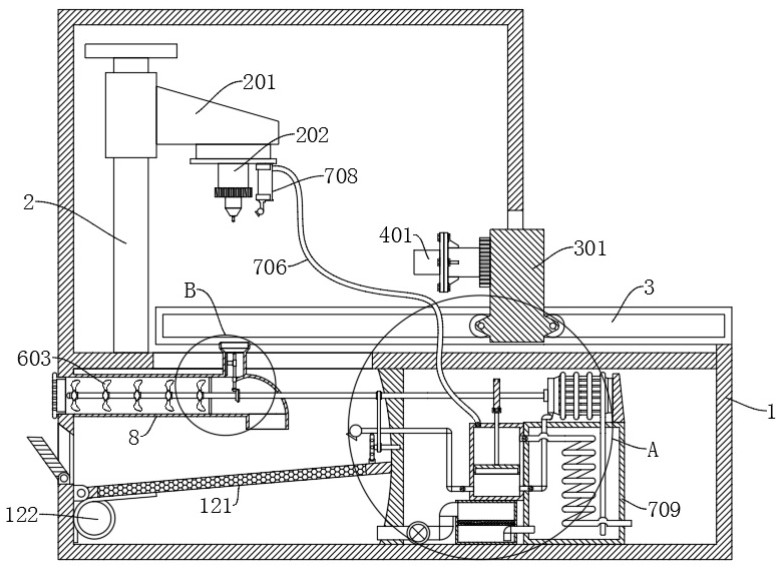
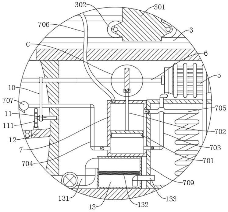
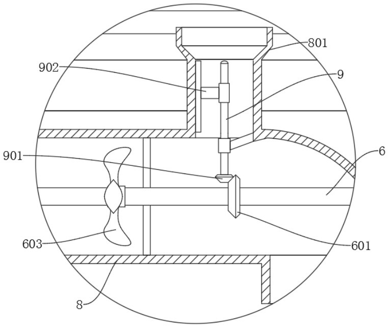
[0036] refer to Figure 1-7 , a high-precision CCD visual positioning laser cutting machine, including a workbench 1 and a high-precision cutting mechanism arranged on the workbench 1, and also includes: a first rotating shaft 6, which is rotatably connected in the workbench 1; a driving part, which is arranged on the workbench 1 The workbench 1 is used to drive the first rotating shaft 6 to rotate; the cylinder 7 is arranged in the workbench 1; wherein, a piston 701 is slidably connected to the cylinder 7, and a water inlet pipe 703 and a drain pipe 704 are provided at the lower end of the cylinder 7, and the upper end of the cylinder 7 An inlet pipe 705 and an exhaust pipe 706 are provided, and the piston 701 slides between the water inlet pipe 703 and the air inlet pipe 705. The ends of the water inlet pipe 703, the drain pipe 704, and the exhaust pipe 706 away from the cylinder 7 are respectively connected with a water tank 709, a first The nozzle 707 and the second nozzle...
Embodiment 2
[0039] refer to Figure 1-7 , a high-precision CCD visual positioning laser cutting machine, which is basically the same as Embodiment 1, furthermore: the high-precision cutting mechanism includes a support frame 2, and the support frame 2 is slidably connected with a fixed frame 201, and the fixed frame 201 is provided with The cutting machine body 202, the cutting machine body 202 is located above the collection bin, the workbench 1 is provided with a slide rail 3, and a robot 301 is slidably connected to the slide rail 3, and the robot 301 is provided with a clamping mechanism for fixing the workpiece. The workpiece to be cut is clamped and fixed by the clamping mechanism, and the robot 301 and the cutting machine body 202 are programmed and controlled by an external control device, so that the cutting machine body 202 and the robot 301 cooperate with each other to perform precise cutting on the workpiece.
Embodiment 3
[0041] refer to figure 1 and Figure 5-7 , a high-precision CCD visual positioning laser cutting machine, which is basically the same as Embodiment 1, furthermore: the clamping mechanism includes a clamping groove 4, a fixing seat 401 is provided at the bottom of the clamping groove 4, and the side wall of the clamping groove 4 Rotationally connected with a two-way screw rod 402, the two ends of the two-way screw rod 402 are symmetrically threaded with a clamping plate 403, the clamping plate 403 is slidably connected in the clamping groove 4, and the limit rod 404 is fixedly connected in the clamping groove 4, clamping The plate 403 is slidingly connected with the limit rod 404, and the clamping plate 403 is an arc-shaped plate or a flat plate. The staff connects the fixed seat 401 with the robot 301 through bolts, and makes the two sets of clamping plates 403 close to each other by turning the two-way screw rod 402 The workpiece is clamped and fixed, and the two-way screw r...
PUM
 Abstract
Description
Claims
Application Information
 - R&D Engineer
- R&D Manager
- IP Professional
- Industry Leading Data Capabilities
- Powerful AI technology
- Patent DNA Extraction
Browse by: Latest US Patents, China's latest patents, Technical Efficacy Thesaurus, Application Domain, Technology Topic, Popular Technical Reports.
© 2024 PatSnap. All rights reserved.Legal|Privacy policy|Modern Slavery Act Transparency Statement|Sitemap|About US| Contact US: help@patsnap.com


