Glass processing device capable of conveniently observing internal processing conditions
A technology for internal processing and processing devices, applied in the directions of transportation and packaging, lighting and heating equipment, chemical instruments and methods, etc., can solve the problems of difficult to observe the internal conditions of the device, occlusion, etc., to improve the utilization rate of water resources and high cooling efficiency , the effect of easy observation
- Summary
- Abstract
- Description
- Claims
- Application Information
AI Technical Summary
Problems solved by technology
Method used
Image
Examples
Embodiment 1
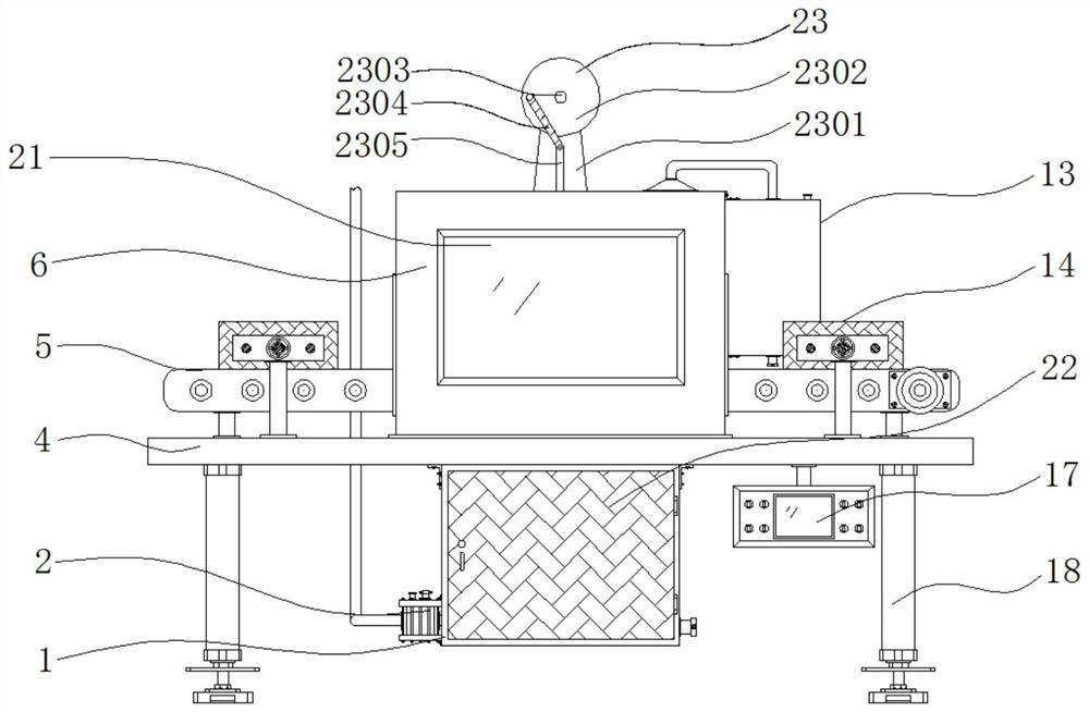
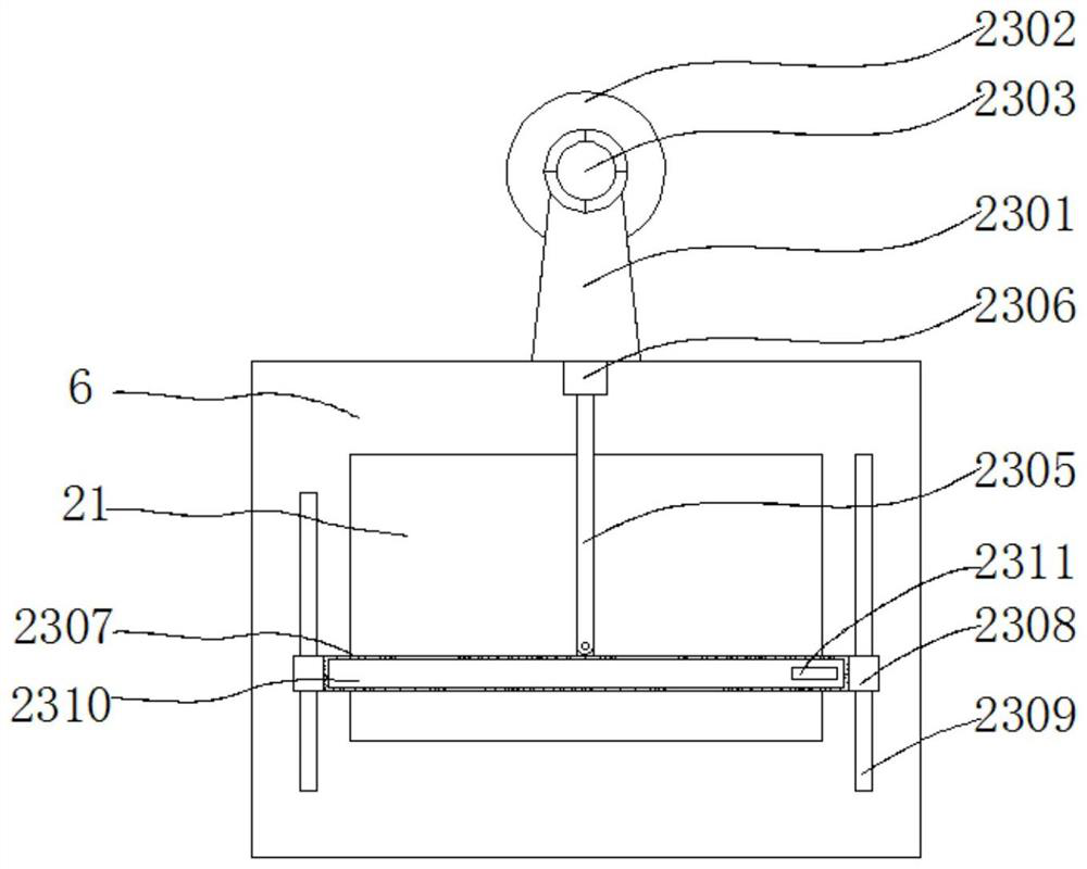
[0043] Embodiment 1: A glass processing device for convenient observation of internal processing conditions, including a bottom plate 4 and a frame body 6, characterized in that: one end of the frame body 6 is fixedly connected with an observation window 21, and the top of the frame body 6 is provided with a rocker assembly 23. The rocker assembly 23 includes a rocker assembly 23, a waist plate 2301, a turntable 2302, a servo motor 2303, a first connecting rod 2304, a second connecting rod 2305, a first slider 2306, a concave housing 2307, a second Slider 2308, slide rail 2309, clip 2310, fastener 2311 and convex cleaning block 2312; the top front end of frame body 6 is fixedly connected with waist-shaped plate 2301, and the top of waist-shaped plate 2301 is connected with rotating disk 2302, and rotating disk 2302 Servomotor 2303 is fixedly connected to the back of the plate, and the servomotor 2303 is fixedly installed on the back of the shaped plate 2301, and the rotating sh...
Embodiment 2
[0045] Embodiment 2: The four corners of the bottom end of the bottom plate 4 are respectively fixedly connected with support columns 18, and the middle position of the top end of the bottom plate 4 is fixedly connected with the frame body 6, and the two sides of the frame body 6 are respectively provided with reserved grooves 7, The middle position of the bottom end of the base plate 4 is fixedly connected with a purification box 1, the bottom end of the purification box 1 side is plugged with a drain port 19, the middle position of the top end of the base plate 4 is provided with a conveying mechanism 5, and one end of the bottom side of the base plate 4 is fixed. The control panel 17 is connected, and the bottom end of the frame body 6 of the base plate 4 is fixedly connected with a water collection bucket 8, and the bottom end of the water collection bucket 8 is fixedly connected with a downpipe 15, and the bottom end of the downwater pipe 15 runs through the bottom plate 4 ...
Embodiment 3
[0048] Embodiment 3: The conveying mechanism 5 is composed of a fixed horizontal plate 501, a rotating shaft 502, a pulley 503, a transmission belt 504, an anti-slip sleeve 505 and a driving motor 506. The fixed horizontal plate 501 is fixedly connected to the two ends of the top of the bottom plate 4 respectively, and the fixed horizontal plate 501 A rotating shaft 502 is evenly and flexibly connected between them, and a drive motor 506 is fixedly connected to one end of the fixed horizontal plate 501. The output end is fixedly connected, and the other end of the rotating shaft 502 runs through the other end of the fixed horizontal plate 501 respectively, and the other end of the rotating shaft 502 is respectively fixedly connected with a pulley 503, and a transmission belt 504 is arranged between the pulleys 503, and the outside of the rotating shaft 502 is fixedly connected with an anti-skid Set 505;
[0049] Fifteen groups of rotating shafts 502 are arranged, and the rotat...
PUM
 Abstract
Description
Claims
Application Information
 - R&D
- Intellectual Property
- Life Sciences
- Materials
- Tech Scout
- Unparalleled Data Quality
- Higher Quality Content
- 60% Fewer Hallucinations
Browse by: Latest US Patents, China's latest patents, Technical Efficacy Thesaurus, Application Domain, Technology Topic, Popular Technical Reports.
© 2025 PatSnap. All rights reserved.Legal|Privacy policy|Modern Slavery Act Transparency Statement|Sitemap|About US| Contact US: help@patsnap.com


