Heat exchange system capable of realizing waste gas recovery

A heat exchange system and waste gas recovery technology, applied in heat exchangers, indirect heat exchangers, heat exchanger types, etc., can solve the problems of less products and low waste gas purification effect.

Pending Publication Date: 2021-08-31
福建亿一智控有限公司
View PDF0 Cites 4 Cited by
  • Summary
  • Abstract
  • Description
  • Claims
  • Application Information

AI Technical Summary

Problems solved by technology

[0005] The purpose of the present invention is to address the deficiencies of the prior art, by setting the first-level purification mechanism to cooperate with the second-level purification mechanism to realize the purification work of the waste gas twice, to keep the continuously input waste gas fully reacting with the continuously input purification liquid, and to improve the reaction efficiency At the same time, the purified liquid in the saturat

Method used


Image

  • Heat exchange system capable of realizing waste gas recovery
  • Heat exchange system capable of realizing waste gas recovery
  • Heat exchange system capable of realizing waste gas recovery

Examples


Embodiment 1

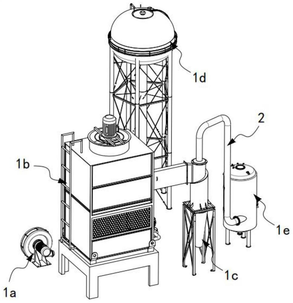
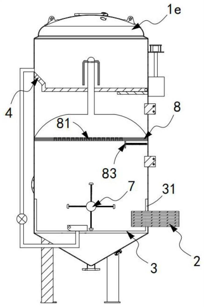
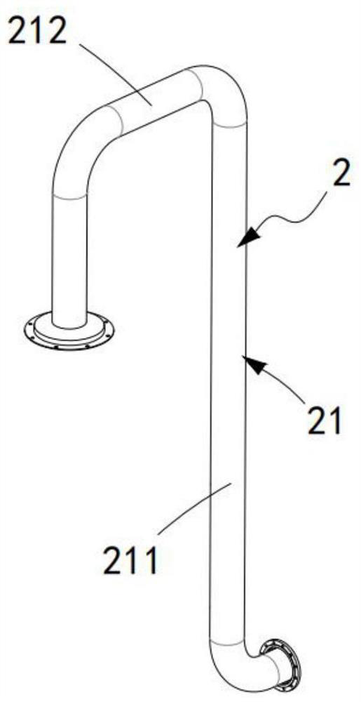
[0068] Such as figure 1 , figure 2 As shown, the exhaust gas recovery heat exchange system includes a fan 1a, a heat exchanger 1b, a rotary separator 1c, a cooling tower 1d, and a gas-liquid mixing tower 1e. The primary purification mechanism 2 arranged in communication with the tower 1e, the secondary purification mechanism 3 arranged in the gas-liquid mixing tower 1e and located at the bottom end, located in the gas-liquid mixing tower 1e and located in the secondary purification mechanism The three-stage purification mechanism 4 above the 3;

[0069] The three-stage purification mechanism 4 controls the switch of the rotary separator air inlet through the first transmission assembly 5 and controls the switching work of the rotary separator liquid outlet a101 through the second transmission assembly 6;

[0070] A purification liquid storage tank is arranged outside the gas-liquid mixing tower 1e, and the purification liquid in the purification liquid storage tank is conti...

Embodiment 2

[0099] Such as Figure 7 to Figure 12 As shown, the components that are the same as or corresponding to those in the first embodiment are marked with the corresponding reference numerals in the first embodiment. For the sake of simplicity, only the differences from the first embodiment will be described below. The difference between this embodiment two and embodiment one is:

[0100] further, such as Figure 7 to Figure 9 As shown, the filter assembly 81 includes:

[0101] A filter plate 811, the filter plate 811 is fixedly arranged on the inner wall of the gas-liquid mixing tower 1e and two groups are arranged up and down;

[0102] A hole blocking plate 812, the hole blocking plate 812 is rotatably arranged between two adjacent filter plates 811;

[0103] A shroud 813, the shroud 813 is fixed above the filter plate 811 and is a hollow structure; and

[0104] A hose 814 , one end of the hose 814 communicates and is fixedly connected with the upper end of the cage 813 , and...


PUM


Abstract

The invention relates to a heat exchange system capable of realizing waste gas recovery. The heat exchange system comprises a fan, a heat exchanger, a rotary separator, a cold water tower and a gas-liquid mixing tower and further comprises a first-stage purification mechanism, a second-stage purification mechanism and a third-stage purification mechanism; the third-stage purification mechanism controls opening and closing of an air inlet of the heat exchanger through a first transmission assembly and controls switching work of a liquid outlet a of the rotary separator through a second transmission assembly; a purification liquid storage tank is arranged outside the gas-liquid mixing tower, and a purification liquid in the purification liquid storage tank is continuously introduced into the first-stage purification mechanism; an output mechanism is arranged in the second-stage purification mechanism, and the output mechanism quantitatively and intermittently conveys the purification liquid into the third-stage purification mechanism; a separation mechanism is arranged below the third-stage purification mechanism. The technical problem that the waste gas purification effect is low due to the fact that products are fewer and fewer due to the fact that reactants of the purification liquid are fewer and fewer after the purification liquid of the gas-liquid mixing tower is subjected to multiple times of reactions is solved.

Description

technical field [0001] The invention relates to the technical field of waste gas recovery, in particular to a heat exchange system for waste gas recovery. Background technique [0002] At present, in my country's large and medium-sized cities, especially in economically developed areas, the amount of industrial waste gas has increased sharply, and the proper treatment of these waste gases has become more and more urgent. A large part of these waste gases are organic waste gases. There are many types of these organic waste gases. In the past, the method of direct discharge was used to deal with these organic waste gases. Contains gaseous organic solvents, direct discharge will cause serious pollution to the atmosphere, and is not conducive to the recycling of organic solvents. [0003] The patent document with the patent number CN2016101275320 discloses a waste gas recovery and heat exchange system, including a fan, a heat exchanger, a rotating separation chamber, a cooling ...

Claims


Application Information

Patent Timeline
IPC IPC(8): F28D21/00B01D53/75B01D53/78B01D53/44B01D53/00B01D53/26B01D53/18B08B9/087
CPCB01D53/002B01D53/18B01D53/265B01D53/44B01D53/75B01D53/78B01D2258/02B08B9/087F28D21/0014
Inventor 章方泽
Owner 福建亿一智控有限公司
Why Eureka
Try Eureka