
Photovoltaic module junction box
A photovoltaic module and junction box technology, applied in the field of junction boxes, can solve the problems of lack of cable auxiliary conduction, easy heat generation of diodes, temperature rise of conductors, etc., to achieve effective direct contact cooling and cooling, eliminate air gaps, and avoid precipitation effects
- Summary
- Abstract
- Description
- Claims
- Application Information
AI Technical Summary
Problems solved by technology
Method used
Image

Examples
Embodiment
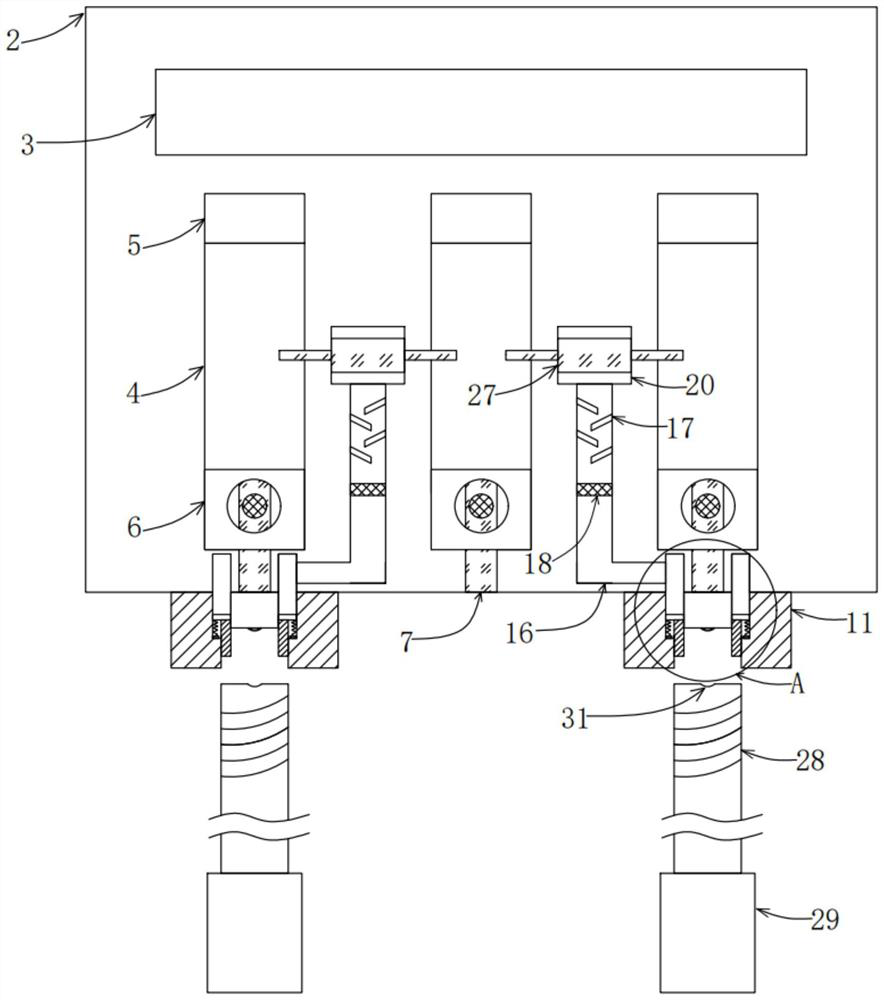
[0034] see Figure 1 to Figure 7 , the present invention provides a technical solution:
[0035] A photovoltaic module junction box, comprising:
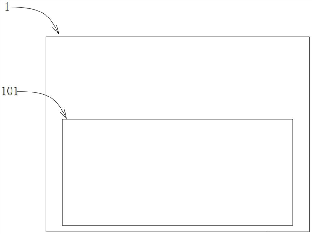
[0036] Cover plate 1, a transparent window 101 is embedded in the cover plate 1, so that the user can observe the inside of the box body 2 without opening the cover plate 1;
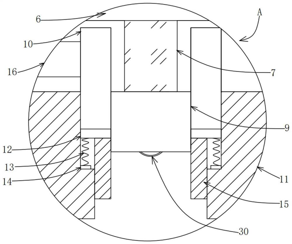
[0037] The box body 2, the box body 2 and the cover plate 1 are fastened and set, which is a detachable setting. The connection between the box body 2 and the cover plate 1 should be provided with a sealing ring to prevent water seepage. Wire port 3, a plurality of electrical conductors 4 are fixedly arranged in the box body 2, one end of the electrical conductors 4 is provided with a jack 5, and one end of the electrical conductor 4 away from the jack 5 is fixedly provided with a connecting wire holder 6, and the connecting wire holder 6 has Conductivity, the lead rod 7 is electrically connected to the connecting wire seat 6, and the lead rod 7 is electrica...
Embodiment 1
[0049] When in use, the cable 28 needs to be installed in the socket 11, specifically, the cable 28 is rotated and pushed, so that the cable 28 rotates along the screw thread inside the socket 11 until the end of the cable 28 touches the conductor. block 9 to achieve communication, and at this time, the elastic conductive reed 30 on the outside of the conductive block 9 just fits into the slot 31 to assist in conduction.
[0050] When the electric cable 28 rotates and advances, it will be pushed to the annular push plate 15, and the annular push plate 15 pushes the annular piston plate 12 inwards, so that the liquid in the hollow ring 10 is extruded outwards. In the state, the isolation piston plate 18 will be pushed to the side close to the bearing seat 20, and then the liquid between the isolation piston plate 18 and the elastic airbag layer 24 will also be squeezed out, and the liquid will enter the storage chamber through the flow tube 19 26. The flow pipe 19 is provided w...
Embodiment 2
[0053] This embodiment is similar to Embodiment 1, the only difference is that in this embodiment, the baffles 21 share the same two groups, and the liquid needs to pass through the two groups of baffles 21 in order to improve the turbulence effect and further avoid There is a problem of layering and sedimentation of fire extinguishing fluid.
PUM
 Abstract
Description
Claims
Application Information