Electromagnetic forming device and forming method based on conductive channel

A conductive channel and electromagnetic forming technology, which is applied in the field of metal forming manufacturing, can solve problems such as poor contact, difficulty in designing the size of the uniform pressure coil, and limited size of the plate to be formed, so as to improve the electromagnetic force, improve the phenomenon of electric sparks, Effect of improving molding quality

Active Publication Date: 2022-02-11
HUAZHONG UNIV OF SCI & TECH
View PDF3 Cites 0 Cited by
  • Summary
  • Abstract
  • Description
  • Claims
  • Application Information

AI Technical Summary

Problems solved by technology

[0004] In view of the defects of the prior art, the purpose of the present invention is to provide an electromagnetic forming device and forming method based on conductive channels, aiming to solve the problem of poor contact during the forming of the traditional internal field uniform pressure coil, difficulties in the size design of the uniform pressure coil or pending forming The problem of limited board size

Method used


Image

  • Electromagnetic forming device and forming method based on conductive channel
  • Electromagnetic forming device and forming method based on conductive channel
  • Electromagnetic forming device and forming method based on conductive channel

Examples


Embodiment Construction

[0040]In order to make the object, technical solution and advantages of the present invention clearer, the present invention will be further described in detail below in conjunction with the accompanying drawings and embodiments. It should be understood that the specific embodiments described here are only used to explain the present invention, not to limit the present invention.

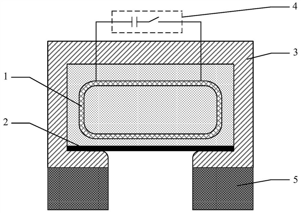
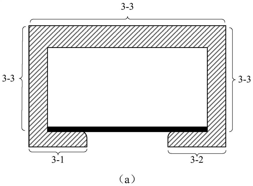
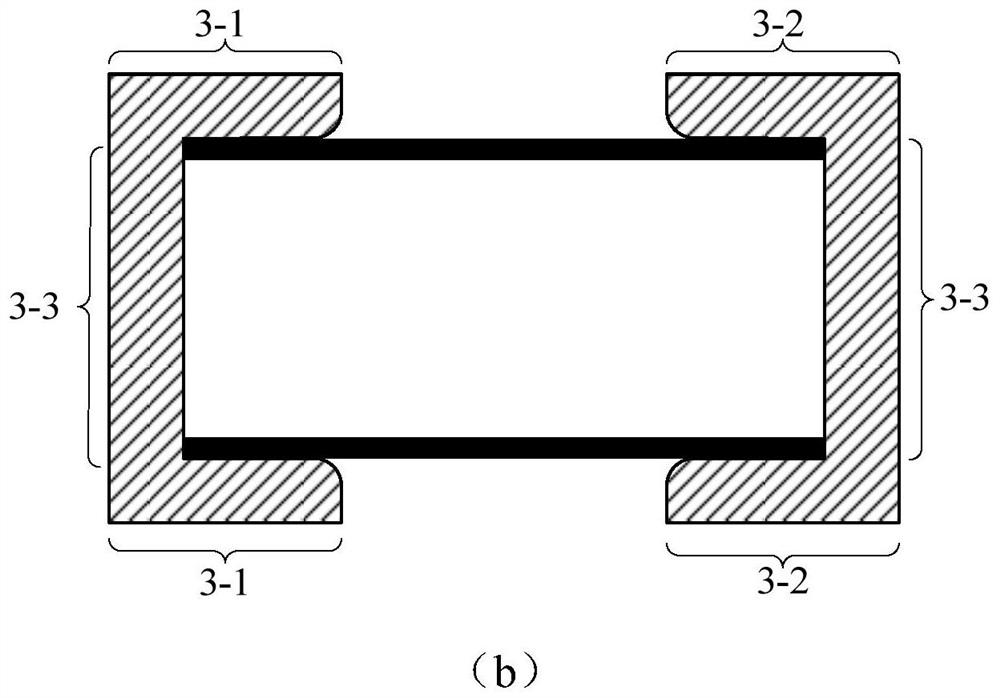
[0041] In one embodiment, the present invention provides an electromagnetic forming device based on a conductive channel, including: a uniform pressure driving coil, a conductive channel, and a mould;

[0042] The conductive channel is placed on one side of the mold; the mold includes a left side area, a right side area and a middle concave area; the conductive channel includes a first sub-conductive channel, a second sub-conductive channel and a third sub-conductive channel; the The first sub-conductive channel and the second sub-conductive channel are respectively placed on one side of the left ar...


PUM


Abstract

The invention provides an electromagnetic forming device and forming method based on a conductive channel, comprising: the conductive channel is placed on one side of the mold; the mold includes a left area, a right area and a central concave area; the conductive channel includes a first And the third sub-conductive channel; the first and second sub-conductive channels are respectively placed on one side of the left area of ​​the mold and one side of the right area of ​​the mold, and the third sub-conductive channel connects the first and second sub-conductive channels to form A circular conductive channel with a notch, and the direction of the notch faces the middle concave area of ​​the mold; the metal workpiece is placed at the gap inside the conductive channel; the metal workpiece and the conductive channel form a conductive loop; the uniform pressure drive coil is placed inside the conductive channel , and placed above the metal workpiece; pass a pulse current to the uniform pressure drive coil, and drive the metal workpiece to deform toward the middle concave area of ​​the mold. The invention reduces the contact resistance formed by poor contact between the metal workpiece and the conductive channel, and improves the forming quality of the workpiece.

Description

technical field [0001] The invention belongs to the field of metal forming and manufacturing, and more specifically relates to an electromagnetic forming device and forming method based on a conductive channel. Background technique [0002] The use of light alloy materials provides an effective way to achieve lightweight industrial production in the fields of automobiles, aerospace, etc., but due to the poor formability and plasticity of commonly used light alloy materials such as aluminum alloys and titanium alloys at room temperature Low, small elastic modulus, the effect of traditional processing technology is not ideal. Studies have shown that high-speed forming technology can effectively improve the formability of light alloys at room temperature. Therefore, electromagnetic forming, as a high-speed forming technology, has been widely used in the processing field of aluminum alloy and other light alloy materials. [0003] In the electromagnetic forming technology of no...

Claims


Application Information

Patent Timeline
Patent Type & Authority Patents(China)
IPC IPC(8): B21D26/14
CPCB21D26/14Y02P10/25
Inventor 李亮王紫叶赖智鹏韩小涛曹全梁
Owner HUAZHONG UNIV OF SCI & TECH
Why Eureka
Try Eureka