
Casting method of high-speed high-power diesel engine cylinder cover

A high-power diesel engine and cylinder head technology, applied in the direction of casting molding equipment, casting molds, casting mold components, etc., can solve the problems of poor filter residue effect, poor sand mold compactness and rigidity, slow cooling speed, etc., to reduce porosity Defects, reduce porosity defects, avoid the effect of heat concentration

Active Publication Date: 2021-09-03
HENAN DIESEL ENGINE IND
View PDF13 Cites 0 Cited by
  • Summary
  • Abstract
  • Description
  • Claims
  • Application Information

AI Technical Summary

Problems solved by technology

[0004]1. Patent name: Diesel engine cylinder head casting method, application number: 200710023424.X, the technical solution of the Chinese patent on the publication date of 2007.11.7 adopts bottom casting, The four ingates are designed to face each other on both sides of the bottom of the cylinder head. The disadvantage is that the molten iron flows from the ingates on both sides to the center during the pouring process of the bottom pouring method, and finally meets at the center, and air holes and slag inclusions are easily formed at the intersection. other casting defects
[0005]2. Patent name: Cylinder head casting process, application number: CN201110107863.5, the technical solution of the Chinese patent on the publication date of 2012.10.31 uses basic phenolic The disadvantage of resin sand molding is that compared with furan resin no-bake sand, basic phenolic resin sand has lower tensile strength at room temperature, a large amount of resin added and a large amount of gas generation.
[0006]3. Patent name: A method for rapid casting of diesel engine cylinder head and sand core assembly, application number: CN201811510152.0, the Chinese patent of publication date 2019.01.25 The technical solution adopts a vertically inserted filter screen installation seat, which is located in the slow-flow slag collection area of ​​molten metal. The disadvantage is that the invention has certain limitations and is suitable for the use of 3D printing to produce cores. At this time, the filter screen seat can There is no draft angle, the gap between the filter screen and the mounting seat is even when installed, and the effect of filtering residue is better. When using the traditional casting method to produce the core, the mold is used. In order to facilitate the mold removal, it is necessary to increase the draft angle on the mold. The size gradually increases with the increase of the height. When the vertical filter screen installation seat is used, the root size is larger than the top size. When the filter screen is installed, the gap with the filter screen seat is large, and the filter residue effect becomes poor
[0007]4. Patent name: One-box two-piece casting process for marine diesel engine cylinder head castings, application number: CN201910552138.5, technology of Chinese patent with publication date 2019.08.23 The scheme adopts: (1) The distribution of the sand molds of the left and right cylinder heads is symmetrical to the center, the runners are set on the center line of the adjacent sides, and the inner runners are set on the adjacent sides. The disadvantage is that the cylinder head adopts the The distribution method, the heat concentration on the adjacent side, the cooling speed is slow, and it is easy to cause loose casting defects in the heat concentration area; (2) The gap between the sand core and the sand mold of the cylinder head outer mold is filled with waste sand, the disadvantage is that the sand mold The tightness and rigidity are poor, which can easily cause poor compactness of the cylinder head matrix
[0008]5. Patent name: A bottom pouring and pouring structure, application number: CN202010604730.8, publication date: 2020.9.22 The technical solution of the Chinese patent is : The filter is set at the bottom of the sprue. The disadvantage is that the liquid flow directly impacts the filter during the pouring of the molten metal. If the weight of the molten iron in the pouring cavity is large, the filter is prone to breakage and cannot be effective. Filter residue effect, easy to cause casting slag inclusion and inclusion effect

Method used


Image

  • Casting method of high-speed high-power diesel engine cylinder cover
  • Casting method of high-speed high-power diesel engine cylinder cover
  • Casting method of high-speed high-power diesel engine cylinder cover

Examples


Embodiment 1

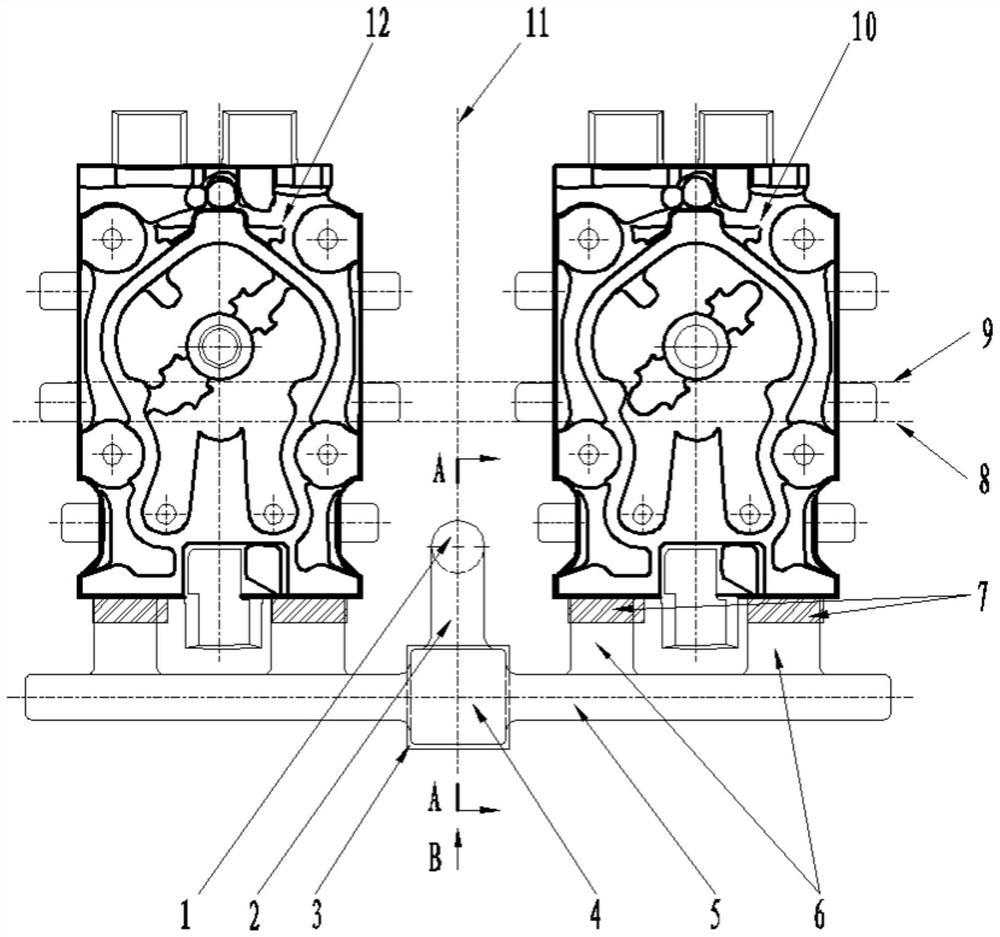
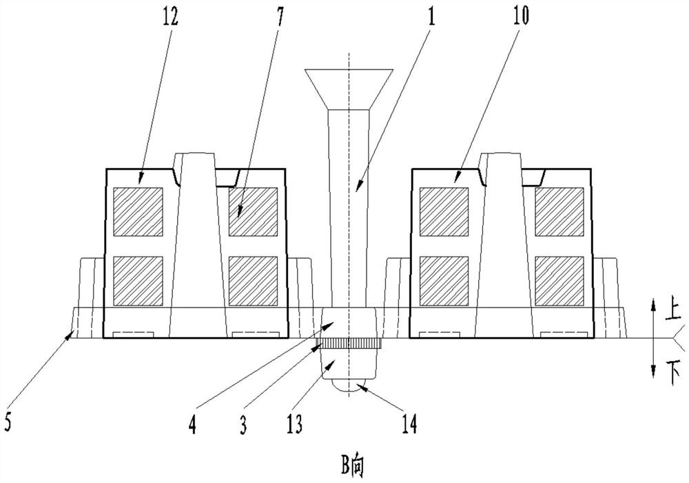
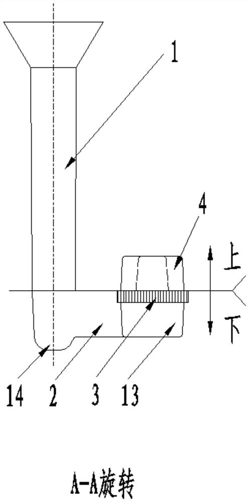
[0045] A casting method for the cylinder head of a high-speed and high-power diesel engine, which can reduce inclusions, pores and loose defects of the cylinder head, improve the internal quality of the cylinder head, and reduce the leakage rate, such as figure 1 , figure 2 , image 3 As shown, specifically set to the following structure:

[0046] Basically, the casting method of this kind of high-speed and high-power diesel engine cylinder head adopts one mold and two pieces for production, so that the two pieces of cylinder head cavities in the sand mold are arranged side by side. The pouring system in the mold used by this method needs to use The molten metal flows downward from the sand mold located on the center line between the two cylinder heads, close to the side of the exhaust end face, and makes the metal liquid be located between the two cylinder head cavities at the exhaust end face The positions in between flow to the left and right respectively and enter the c...

Embodiment 2

[0060] This embodiment is further optimized on the basis of the foregoing embodiments, and particularly adopts the following configuration structure:

[0061] In step S3, determine the line connecting the centers of the two cylinder heads, that is, the center line 9 of the cylinder head is located on one side of the center line 8 in the length direction of the sand mold as a whole, and there are castings, runners and ingates in the width direction of the sand mold. The center line of the cover is offset to one side to reserve a place for the gating system design on the other side, avoiding one side being too close to the edge.

[0062] The centerline 9 of the two cylinder heads is on one side of the centerline 8 in the sand mold length direction, with an offset of 30mm. See figure 1 .

Embodiment 3

[0064] This embodiment is further optimized on the basis of the above-mentioned embodiment, and particularly adopts the following setting structure: In step S4, determine that the number of inrunners of a single cylinder head is set to two, so that the position of the inrunner of a single cylinder head Two locations in the lateral direction of the exhaust end face. A single cylinder head is equipped with two inrunners 6, so that less molten metal flows through a single inrunner 6, which can reduce the edge of the inrunner 6 from being scoured by the molten metal, and prevent the core near the inrunner 6 from being washed away. Sand inclusion defects or even leakage will occur in the cylinder head; in addition, when the two ingates are poured, the heat near the single ingate 6 is relatively small, so as to avoid local overheating and reduce the tendency of loose defects. In order to increase the cooling speed of the exhaust end face and ensure the overall uniform solidification...


PUM


Abstract

The invention provides a casting method of a high-speed and high-power diesel engine cylinder cover, relates to the technical field of internal combustion engines, and solves the problems of inclusion, air holes and looseness of the cylinder cover. According to the method, one mold and two parts are adopted for production, and two cylinder cover cavities in a sand mold are distributed side by side left and right; and molten metal separately flows leftwards and rightwards from the position, between the two air cylinder cover cavities located at one side of the exhaust end surface, of the sand mold and enters the air cylinder cover cavities at the corresponding sides, and the corresponding air cylinder cover cavities are filled with the molten metal from bottom to top separately. According to the method, the defects of inclusion, air holes and looseness of the cylinder cover can be reduced, the internal quality of the cylinder cover can be improved and the leakage rate can be reduced.

Description

technical field [0001] The invention relates to the technical field of internal combustion engines, in particular to a casting method for a cylinder head of a high-speed and high-power diesel engine. Background technique [0002] The cylinder head is one of the important parts of the diesel engine parts. The cylinder head of the high-speed and high-power diesel engine has a compact appearance and a complex structure, including intake passages, exhaust passages, cooling water chambers, etc., and is subjected to high temperature and impact during operation. , It is required that the internal structure of the cylinder head is dense, and there should be no defects such as looseness, slag inclusions, pores, and leakage. [0003] The applicant searched domestic and foreign technical novelties on the diesel engine cylinder head casting technology and found that: [0004] 1. Patent name: Diesel engine cylinder head casting method, application number: 200710023424.X, the technical s...

Claims


Application Information

Patent Timeline
Patent Type & Authority Applications(China)
IPC IPC(8): B22C9/02B22C9/08
CPCB22C9/02B22C9/082B22C9/086
Inventor 裴泽辉李光辉曹德水白小旺潘红陈冬玲吴红光郭兰英郭新征
Owner HENAN DIESEL ENGINE IND
Learn More