A component of a casting tundish impurity removal and flow control device

A technology of tundish and components, which is applied in the direction of casting equipment, casting molten material container, manufacturing tools, etc., can solve the problems of low removal rate of inclusions, limited ability of inclusion movement track, difficult separation and floating, etc., to achieve high temperature resistance Good thermal shock performance, improved collision probability, and simple overall structure

Active Publication Date: 2022-05-13
WUHAN UNIV OF SCI & TECH +1
View PDF5 Cites 0 Cited by
  • Summary
  • Abstract
  • Description
  • Claims
  • Application Information

AI Technical Summary

Problems solved by technology

However, due to the simple structure of the barrage, the ability to change the trajectory of inclusions is limited, and the removal rate of inclusions is not high, especially small-sized inclusions, which basically follow the movement of the molten metal and are difficult to separate and float from the molten metal

Method used


Image

  • A component of a casting tundish impurity removal and flow control device
  • A component of a casting tundish impurity removal and flow control device
  • A component of a casting tundish impurity removal and flow control device

Examples


Embodiment 1

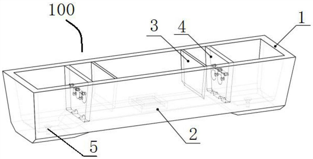
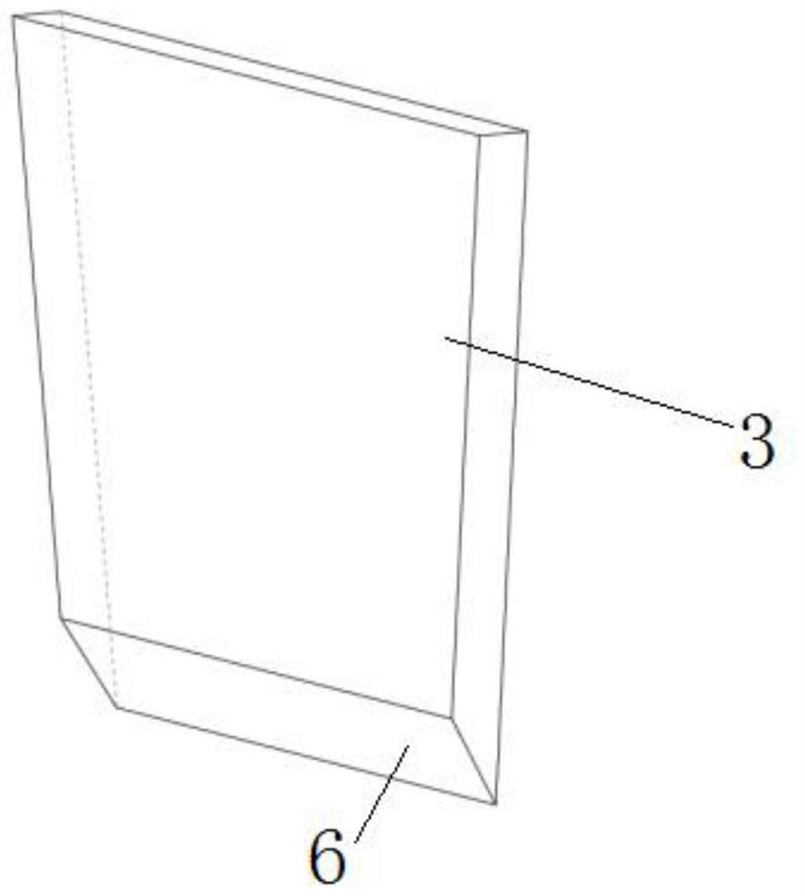
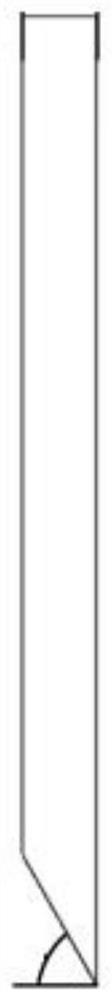
[0030] The structure of a casting tundish removal and flow control device assembly 100 provided in this embodiment is as follows: figure 1 As shown, it includes two weirs 3 and two filters 4 vertically arranged in the tundish 1, a turbulence suppressor 2 is arranged at the inner bottom of the tundish 1, and two symmetrical tundish nozzles are opened at both ends of the bottom of the tundish 1 5. A weir 3 and a filter 4 are arranged between the turbulence suppressor 2 and each tundish nozzle 5, the bottom of the weir 3 is provided with an upflow inclined surface 6, and the bottom of the filter 4 is symmetrically provided with two horizontally arranged Semi-circular frustum-shaped discharge hole 7, two tapered holes 8 are provided on the upstream surface of the filter 4, and three circular holes 9 are provided on the backflow surface of the filter 4, and the passage between the tapered holes 8 and the circular holes 9 The circular channel 10 is connected; the surface of the weir...

Embodiment 2

[0036]The structure of a casting tundish removal and flow control device assembly provided in this embodiment is the same as that of Embodiment 1, except that the chemical composition of the weir 3 and the filter 4 is MgO 98wt%, SiO 2 1wt%, ZrO 2 1 wt%, the distance between the vertical center plane of the weir 3 and the vertical center plane of the filter 4 is equal to 800 mm. The distance between the center of the circular hole 9 on the backflow surface of the filter 4 and the free surface of the molten metal is 80 mm.

[0037] The weir 3 has a thickness of 90mm.

[0038] The thickness of the filter 4 is 180mm, the diameter of the tangential circle of the conical hole 8 at the end face of the upstream surface is 160mm, the diameter of the tangential circle of the conical hole 8 and the connection end of the circular channel 10 is 60mm, and the two ends of the conical hole 8 are large circles The vertical distance between the small circle and the small circle is 50mm, the...


PUM

PropertyMeasurementUnit
thicknessaaaaaaaaaa

Abstract

The invention discloses a casting tundish impurity removal and flow control device assembly, which relates to the technical field of metal casting; it includes a weir and a filter vertically arranged in the tundish, the bottom of the weir is provided with a flow-facing inclined surface, and the filter The bottom of the filter is symmetrically provided with two horizontally arranged semi-circular frustum-shaped discharge holes, the upstream surface of the filter is provided with two conical holes, and the backflow surface of the filter is provided with three circular holes. The shape hole and the circular hole are connected by a circular channel; the surface of the weir, the surface of the filter, the circular hole, the tapered hole, the semi-circular truncated discharge hole and the wall of the circular channel are all coated with a layer of micro-nano oxide functional coating. The impurity removal and flow control device component of the casting tundish provided by the invention has high temperature thermal shock resistance, high inclusion removal rate and low cost.

Description

technical field [0001] The invention relates to the technical field of metal casting, in particular to a casting tundish impurity removal and flow control device assembly. Background technique [0002] The cleanliness of molten metal has an important influence on improving the mechanical properties and mechanical properties of metal castings. With the development of my country's economy and society, the performance requirements of castings and subsequent processing products are increasing day by day. It has become the research focus of metallurgists to reduce non-metallic inclusions in molten metal by various means. [0003] The tundish is a refractory container used in the metal casting process. It is used as a buffer container between the refining ladle and the crystallizer. It first receives the molten metal poured from the refining ladle, and then distributes it to each crystallizer through the tundish nozzle. to go. In order to prolong the movement time of the molten ...

Claims


Application Information

Patent Timeline
Patent Type & Authority Patents(China)
IPC IPC(8): B22D41/00B22D43/00
CPCB22D41/00B22D43/00
Inventor 李光强王强肖爱达谭憧黄奥鄢文陈振文
Owner WUHAN UNIV OF SCI & TECH
Why Eureka
Try Eureka