Automatic polishing machine for surface of long drill rod

An automatic polishing and drill rod technology, which is used in surface polishing machine tools, grinding/polishing equipment, grinding/polishing safety devices, etc. Quality and the effect of improving utilization efficiency

Active Publication Date: 2021-09-03
GUIYANG JIESHENG TECH IND DEV
View PDF15 Cites 2 Cited by
  • Summary
  • Abstract
  • Description
  • Claims
  • Application Information

AI Technical Summary

Problems solved by technology

[0002]In mining engineering equipment, it is very important to process long drill rods with a length-to-diameter ratio greater than 10 times, and its processing quality directly affects the final use performance of the drill rod Requirements have always been valued by manufacturers. In order to improve the performance of this type of parts, the surface of this type of long drill rod needs to be treated. For solid long drill rods, it is generally necessary to polish the surface of the drill rod. The prior art Generally, the surface of the drill rod is polished by spraying the corresponding polishing liquid onto the surface of the drill rod. However, due to the long length of the drill rod, the large mass and the hard surface texture, if the hardness of the components in the polishing liquid is too low, it will affect the quality of the drill rod. Surface polishing quality, in addition, for some stubborn thorns on the surface of the drill rod washed away by the polishing fluid, under the action of water tension, or under the impact of the polishing fluid itself, for example, when the polishing fluid scouring force always along the stubborn When the thorns are in the normal direction, the stubborn thorns are not easy to fall off, which will affect the quality of the surface polishing of the drill rod

Method used


Image

  • Automatic polishing machine for surface of long drill rod
  • Automatic polishing machine for surface of long drill rod
  • Automatic polishing machine for surface of long drill rod

Examples


Embodiment Construction

[0021] The technical solution of the present invention is further described below, but the scope of protection is not limited to the description.

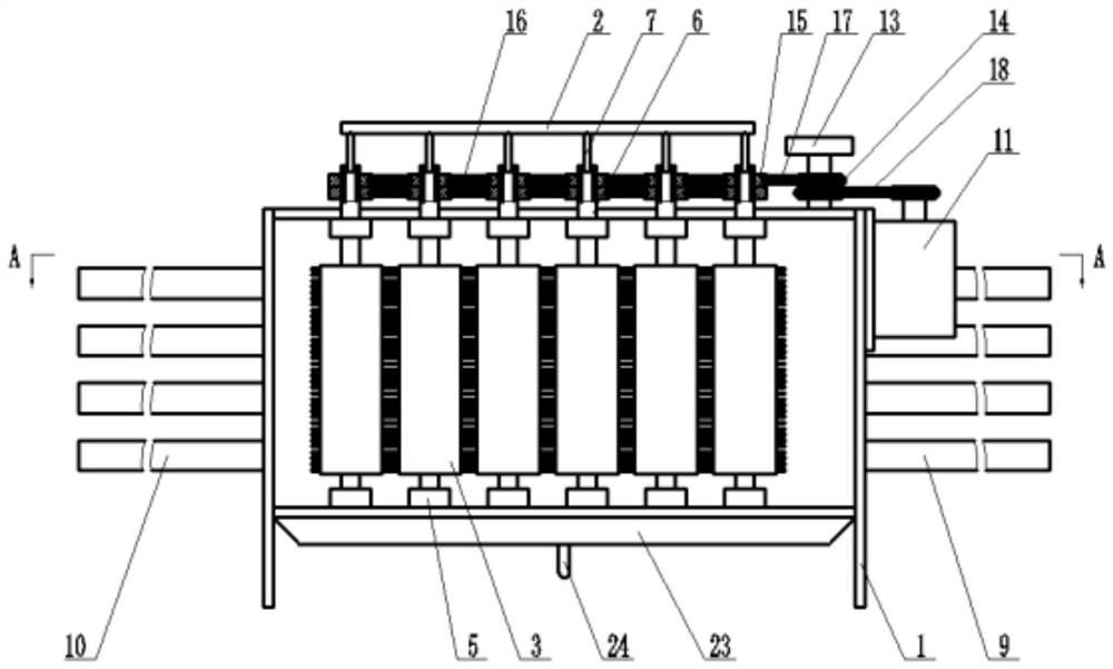
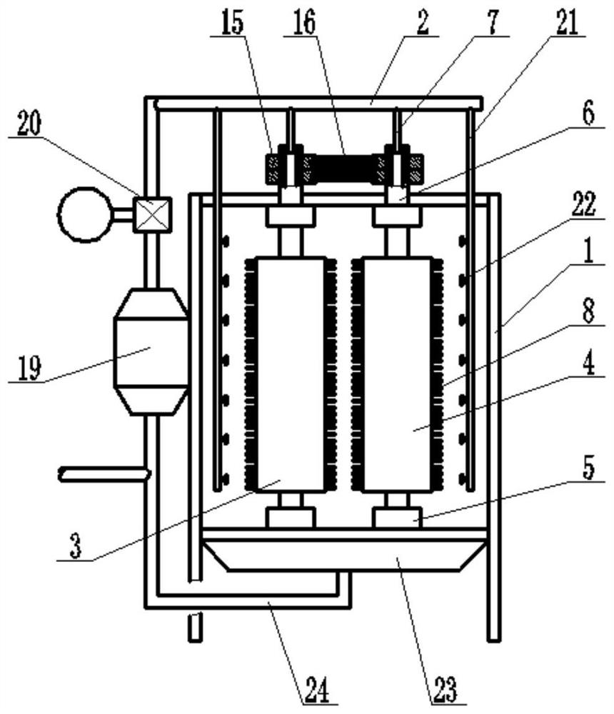
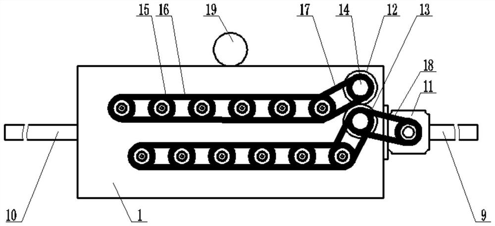
[0022] Such as figure 1 , figure 2 , image 3 with Figure 4 As shown, the present invention provides an automatic polishing machine for the surface of a long chisel, comprising a case shell 1, a liquid supply main pipe 2, a plurality of rollers A3 and a plurality of rollers B4, and the upper and lower ends of roller A and roller B4 respectively pass through The bearing seat 5 is installed in the box shell 1, the liquid inlet pipe 6 is fixedly connected to the roller A3 and the roller B4, and a plurality of distribution pipes 7 are connected to the liquid supply main pipe 2, and each distribution pipe 7 passes through the use of rolling bearings. Inserted in the liquid inlet pipe 6, the outer peripheral surfaces of the roller A3 and the roller B4 are provided with injection holes, and the outer peripheral surfaces of the roller...


PUM


Abstract

The invention provides an automatic polishing machine for the surface of a long drill rod. The automatic polishing machine comprises a box shell, a liquid supply main pipe, a plurality of rollers A and a plurality of rollers B, wherein the upper ends and the lower ends of the rollers A and the rollers B are arranged in the box shell through bearing seats correspondingly, and liquid inlet pipes are fixedly connected to the rollers A and the rollers B correspondingly; a plurality of distribution pipes are further connected to the liquid supply main pipe, and each distribution pipe is inserted into the corresponding liquid inlet pipe through a rolling bearing; spraying holes are formed in the outer circumferential faces of the rollers A and the outer circumferential faces of the rollers B; and bristles are fixedly connected to the outer circumferential faces of the rollers A and the outer circumferential faces of the rollers B. By the adoption of the technical scheme, the long drill rod is clamped between the rollers A and the rollers B to be conveyed, the surface of the drill rod is scoured through polishing liquid thrown out of the rollers and polishing liquid directly sprayed out of a spray head, and stubborn arris thorns attached to the surface of the drill rod are swept away through the bristles, so that the polishing quality is improved; and the polishing liquid circularly flows, so that the utilization efficiency of the polishing liquid is improved.

Description

technical field [0001] The invention belongs to the technical field of mechanical processing equipment, in particular to an automatic polishing machine for the surface of a long drill rod. Background technique [0002] In mining engineering equipment, it is very important to process long drill rods with an aspect ratio greater than 10 times. The processing quality directly affects the final performance requirements of the drill rods, and has always been valued by manufacturers. The use performance of this type of long drill rod needs to be treated on the surface. For solid long drill rods, the surface of the drill rod generally needs to be polished. In the prior art, the corresponding polishing liquid is sprayed onto the drill rod surface to achieve alignment The polishing of the surface of the rod, however, due to the long length of the drill rod, the large mass and the hard surface texture, if the hardness of the components in the polishing solution is too low, it will aff...

Claims


Application Information

Patent Timeline
Patent Type & Authority Applications(China)
IPC IPC(8): B24B29/00B24B27/00B24B55/00B24B57/00B24B57/02
CPCB24B29/005B24B27/0076B24B57/02B24B57/00B24B55/00Y02P70/10
Inventor 韩阳黄献萩艾泽钟
Owner GUIYANG JIESHENG TECH IND DEV
Why Eureka
Try Eureka