
High-leg furnace end with uniform gas mixing function

A burner and gas mixing technology, which is used in household stoves/stoves, gaseous heating fuels, household heating, etc., can solve the problems of affecting combustion efficiency, flame drift, flame instability, etc., to increase the heating area and improve the use effect. , The effect of preventing gas backflow

Inactive Publication Date: 2021-09-03
江西发扬实业有限公司
View PDF0 Cites 1 Cited by
  • Summary
  • Abstract
  • Description
  • Claims
  • Application Information

AI Technical Summary

Problems solved by technology

[0005] In order to overcome the shortcomings of the damper existing in the prior art, which avoids the outflow of gas, but easily leads to unstable flames or flame drift, which affects combustion efficiency, the technical problem is to provide a method that does not require a damper, avoids unstable flames, and drives the gas Stable output, ensuring combustion efficiency, and preventing gas backflow at the same time, ensuring safety with a tall burner head with uniform gas mixture

Method used


Image

  • High-leg furnace end with uniform gas mixing function
  • High-leg furnace end with uniform gas mixing function
  • High-leg furnace end with uniform gas mixing function

Examples


Embodiment 1

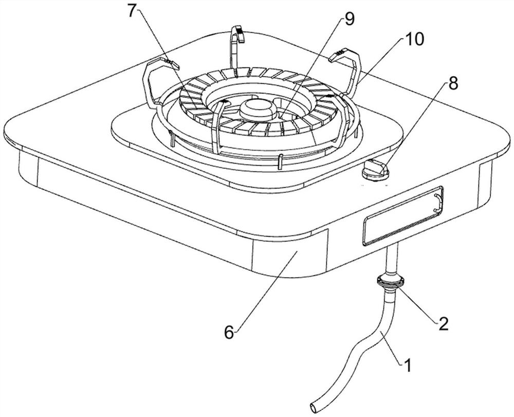
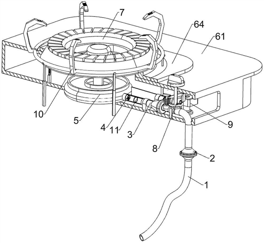
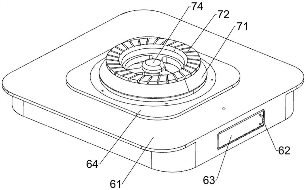
[0026] A tall stove top with a homogeneous gas mixture, such as figure 1 , figure 2 , image 3 and Figure 7 As shown, it includes a gas hose 1, a flame arrester 2, a gas pipeline 3, a turbine 4, a burner 5, a placement mechanism 6 and a stove assembly 7, and a placement mechanism 6 is provided inside the equipment, and a stove is arranged on the top of the placement mechanism 6. Component 7, a furnace head 5 is arranged in the placement mechanism 6, a gas transmission pipeline 3 is connected to the right side of the furnace head 5, a flame arrester 2 is provided at the bottom of the gas transmission pipeline 3, and a gas connection hose 1 is provided at the bottom of the flame arrester 2. A turbine 4 is rotatably arranged between the inner walls of the left part of the pipeline 3 .

[0027] The placement mechanism 6 includes an installation slot plate 61, a handle bar 62, a partition door 63, and an installation plate 64. The top of the installation slot plate 61 is embed...

Embodiment 2

[0031] On the basis of Example 1, such as figure 1 , figure 2 , Figure 4 and Figure 5 As shown, it also includes an air delivery adjustment mechanism 8, and the air delivery adjustment mechanism 8 includes a mounting seat 81, an installation shaft 82, an adjustment knob 83, a first connecting rod 84, a first wedge 85, and a second wedge 86. , the first back-moving spring 87 and the plug post 88, the right side of the bottom of the installation groove plate 61 is provided with an installation seat 81, the top of the installation seat 81 is rotatably provided with an installation shaft 82, the installation shaft 82 passes through the installation groove plate 61, and the installation shaft 82 An adjustment knob 83 is provided on the top, a first connecting rod 84 is provided on the rear side of the middle part of the installation shaft 82, a first wedge-shaped block 85 is provided on the rear side of the first connecting rod 84, and a blocking column 88 is provided slidingl...

Embodiment 3

[0035] On the basis of Example 2, such as figure 1 , figure 2 , Figure 6 and Figure 8 As shown, it also includes a uniform heating mechanism 10 for cooking utensils. The uniform heating mechanism 10 for cooking utensils includes a guide groove plate 101, a placement block 102, a second return spring 103 and a support block 104. The bottom of the inner wall of the installation groove plate 61 is provided with a plurality of guide grooves Plate 101, the guide groove plate 101 is slidably connected with a placement block 102, the placement block 102 is slidably connected with the top of the installation groove plate 61, and a second return spring 103 is connected between the bottom of the placement block 102 and the bottom of the inner wall of the guide groove plate 101, A supporting block 104 is placed between the tops of the placing blocks 102 .

[0036] Also includes a one-way gas transmission mechanism 11, the one-way gas transmission mechanism 11 includes a rotating sh...


PUM


Abstract

The invention relates to a high-leg furnace end, and particularly relates to a high-leg furnace end with a uniform gas mixing function. The high-leg furnace end with the uniform gas mixing function mainly aims at achieving the effects that an air door is not needed, flame instability is avoided, fuel gas is driven to be stably output, the combustion efficiency is guaranteed, meanwhile, fuel gas backflow is prevented, and safety is guaranteed. The high-leg furnace end with the uniform gas mixing function comprises a gas receiving hose, a flame arrester, a gas conveying pipeline, a turbine, a furnace end, a containing mechanism and a furnace assembly, wherein the containing mechanism is arranged in the high-leg furnace end, the furnace assembly is arranged on the top of the containing mechanism, the furnace end is arranged in the containing mechanism, one side of the furnace end is connected with the gas conveying pipeline, the flame arrester is arranged at the bottom of the gas conveying pipeline, the gas receiving hose is arranged at the bottom of the flame arrester, and the turbine is rotationally arranged between the inner walls of the gas conveying pipeline. By arranging the containing mechanism and the furnace assembly, fuel gas is driven to flow out of the furnace end through the gas conveying pipeline, kindling is driven to make contact with the fuel gas to cause fire, and the basic function is achieved in cooperation with use of the furnace end.

Description

technical field [0001] The invention relates to a tall stove head, in particular to a tall stove head with uniform gas mixture. Background technique [0002] At present, during the use of the blower type gas burner on the market, the blower fails, and the gas flows out along the pipeline of the blower, causing poisoning, which poses a relatively large safety hazard. [0003] Therefore, in order to better control the combustion flame and improve combustion efficiency, a damper is provided in the air duct of the burner, but when the position of the damper changes slightly, the air intake of the air duct will immediately change significantly, making the mixing The imbalance of the gas ratio will lead to the phenomenon of flame instability or flame drift, which will affect the combustion efficiency. [0004] Therefore, it is necessary to design a high-leg burner head with uniform gas mixture that does not need a damper, avoids flame instability, drives stable gas output, ensure...

Claims


Application Information

Patent Timeline
IPC IPC(8): F24C3/00F24C3/08F24C3/12
CPCF24C3/002F24C3/122F24C3/082
Inventor 楼发扬
Owner 江西发扬实业有限公司
Learn More