System for smart coupling between a road implement and a tractor vehicle, system and method for managing the actuation of auxiliary traction on road implements
An auxiliary traction and management system technology, applied in the field of mechanical and electronic engineering, can solve the problems of no public management application, no mention of analysis, etc., to achieve the effects of reducing demand, improving energy efficiency, and reducing heat load
- Summary
- Abstract
- Description
- Claims
- Application Information
AI Technical Summary
Problems solved by technology
Method used
Image
Examples
example 1
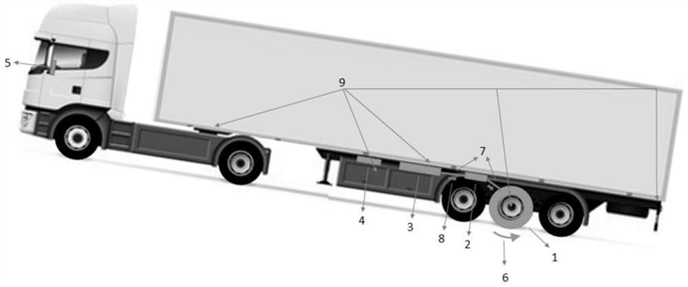
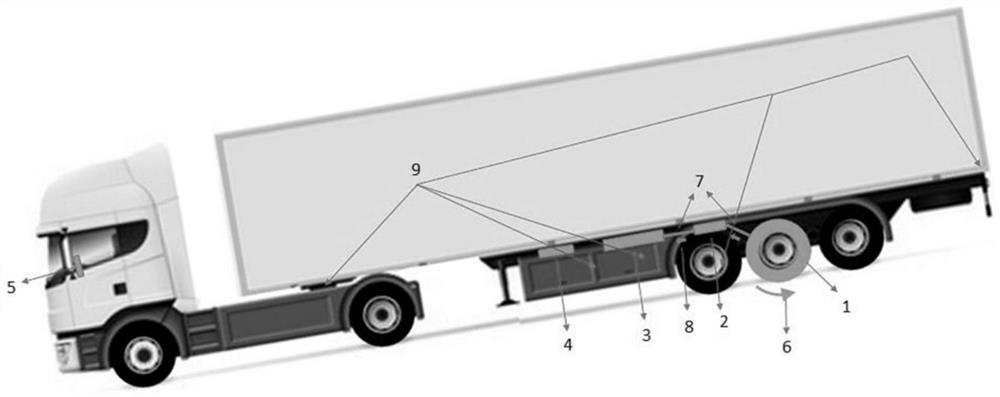
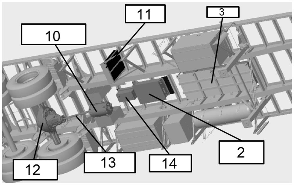
[0187] Example 1 – Electric traction and regenerative braking management system on road equipment
[0188] The examples shown here are only intended to illustrate one of many ways of carrying out the invention, but not to limit the scope of the invention.
[0189] For the demonstration of the concept of the present invention, a number of initial assumptions were considered, focusing on system safety and targeting optimal operating conditions to reduce fuel consumption and extend component life. This assumption refers to: developing a control system such that road equipment is coupled to the towing vehicle without changing the towing vehicle; implementing indirect sensing, mainly so that there is a safety redundancy in the system; the control system (algorithm) is designed so that the semi-trailer (equipment) Can be operated independently of the towing vehicle; all sensors and signals used as control parameters must be carried on the semi-trailer.
[0190]Furthermore, the al...
example 2
[0206] The HMI can also be configured with specific modes for each user, for example for a fleet owner or driver. Based on this, actions can be configured according to the needs of the action. exist Figure 51 In , one of several architectural possibilities of the system is shown, "normal", "urban", "accelerated", "charging" and "disabled" modes are available. In this possible architecture, a hierarchical control system is shown where the Pilotage layer is more internal and runs whenever the system boots, ie the Pilotage layer does not run in "disabled" mode. Piloting is just blocks from the navigation layer. GPS feedback should only occur on known, predetermined routes. In other routes / conditions, the system must be set to one of the selected modes (normal, city, acceleration). Example 2 - Long combination vehicle provided with safe electric traction and regenerative braking management system
[0207] Form electric traction and regenerative braking management systems on...
example 3
[0240] Example 3 – Control system for electric traction equipment with drive controls in the driver's cab
[0241] In this test, the operation of the system is controlled by an operating panel (5) located inside the compartment of the towing vehicle, which is only constructed in a simplified manner for carrying out the test, as Figure 49 and Figure 50 shown. On the panel (5), the E1 button is the emergency button and shuts down the entire system, the B1 button executes the operating mode command, the M button turns on the engine in traction mode, thus pulling the combination and consuming energy, the button N keeps the engine in neutral mode, Button F starts the engine in braking mode, thereby braking the combination and regenerating energy, button B2 defines the power modes (I, II and III stages), and button B3 designates manual or automatic operating mode, where the automatic control of the operating mode is Done by the algorithm, the L1 button refers to the operation ...
PUM
 Abstract
Description
Claims
Application Information
 - R&D
- Intellectual Property
- Life Sciences
- Materials
- Tech Scout
- Unparalleled Data Quality
- Higher Quality Content
- 60% Fewer Hallucinations
Browse by: Latest US Patents, China's latest patents, Technical Efficacy Thesaurus, Application Domain, Technology Topic, Popular Technical Reports.
© 2025 PatSnap. All rights reserved.Legal|Privacy policy|Modern Slavery Act Transparency Statement|Sitemap|About US| Contact US: help@patsnap.com


