Rivet feeding mechanism for automatic drilling and riveting system and manufacturing process

An automatic drilling and riveting technology, which is applied in the field of rivet assembly equipment, can solve the problems of inability to realize the orderly arrangement of large quantities of rivets, poor precision, and low work efficiency, so as to reduce labor costs, improve efficiency and accuracy, and improve work efficiency. efficiency effect

Active Publication Date: 2021-09-07
宜兴市鑫煜科技有限公司
View PDF8 Cites 0 Cited by
  • Summary
  • Abstract
  • Description
  • Claims
  • Application Information

AI Technical Summary

Problems solved by technology

[0004] However, the rivet feeding mechanism in the prior art has the following defects during use: the orderly arrangement of a large number of rivets cannot be realized; when a single rivet is put into the riveting station, the accuracy is poor; only a single rivet can be put in , lower work efficiency

Method used


Image

  • Rivet feeding mechanism for automatic drilling and riveting system and manufacturing process
  • Rivet feeding mechanism for automatic drilling and riveting system and manufacturing process
  • Rivet feeding mechanism for automatic drilling and riveting system and manufacturing process

Examples


Embodiment 1

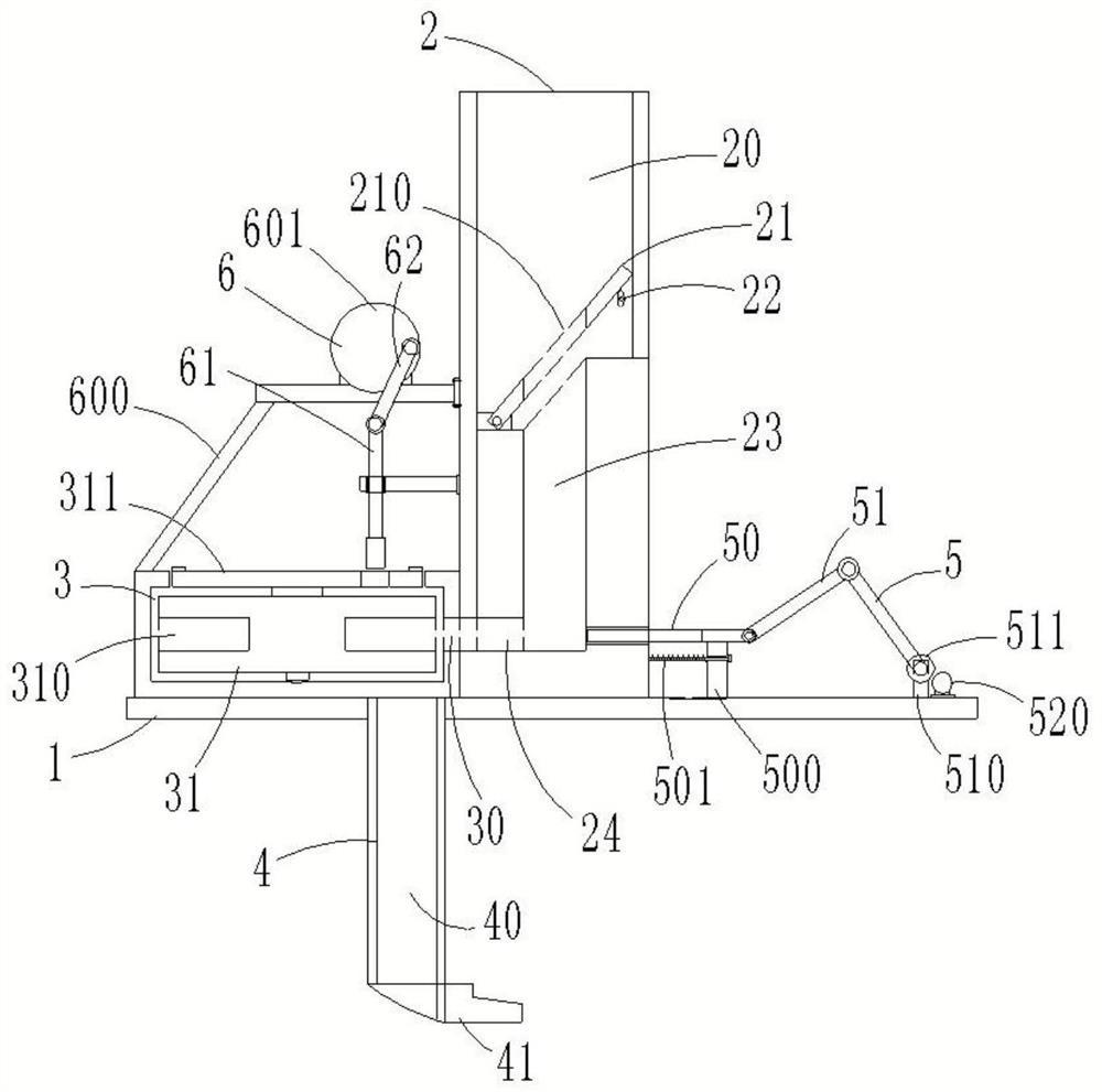
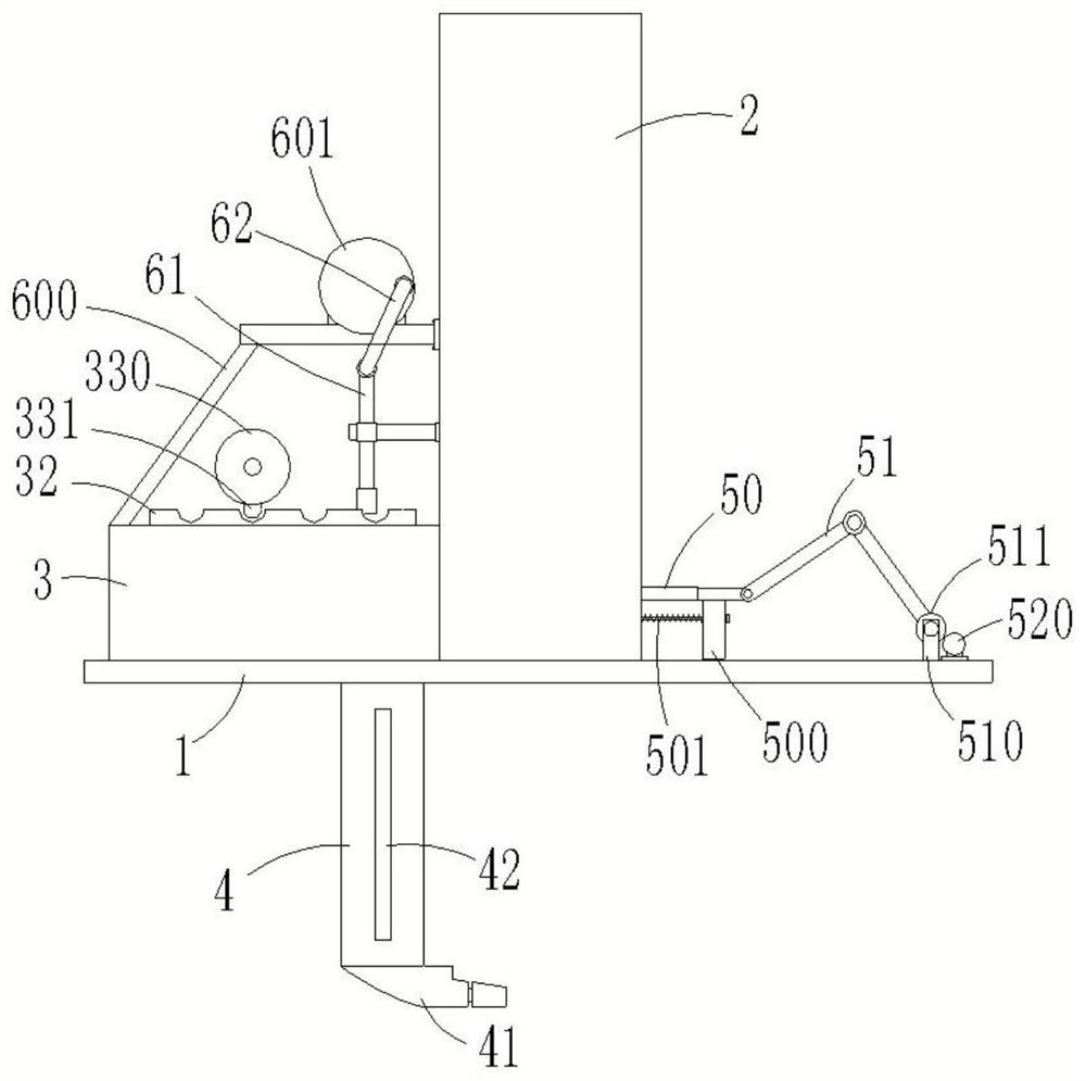
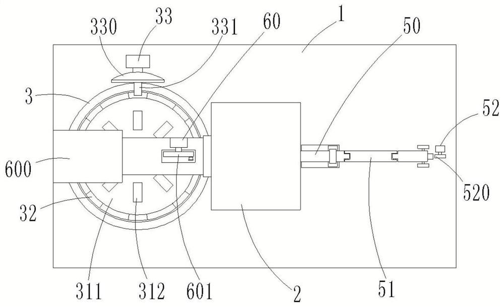
[0039] Embodiment 1: as figure 1 , 2 , A rivet feeding mechanism for automatic drilling and riveting systems shown in 3 and 4, including a mounting plate 1, a nail storage box 2, a conversion box 3, a nail input barrel 4, a first ejector assembly 5, a second ejector Out of the assembly 6 and the controller, the nail storage box 2 is fixedly arranged on the installation plate 1, and the upper end of the nail storage box 2 is provided with a storage cavity 20 and a vibrating plate 21. One end of 21 is articulated with the inner wall of the storage chamber 20, the other end is connected with the storage chamber 20 with a vibrating motor 22, the vibrating plate 21 is provided with a blanking hole 210, and the inner lower end of the nail storage box 2 is vertically provided with a first conveying trough 23. The lower end of the nail storage box 2 is horizontally provided with a first ejection groove 24 that is connected to the first conveying groove 23;

[0040] Such as figure ...

Embodiment 2

[0053] Embodiment 2: as figure 1 , 2 , A rivet feeding mechanism for automatic drilling and riveting systems shown in 3 and 4, including a mounting plate 1, a nail storage box 2, a conversion box 3, a nail input barrel 4, a first ejector assembly 5, a second ejector Out of the assembly 6 and the controller, the nail storage box 2 is fixedly arranged on the installation plate 1, and the upper end of the nail storage box 2 is provided with a storage cavity 20 and a vibrating plate 21. One end of 21 is articulated with the inner wall of the storage chamber 20, the other end is connected with the storage chamber 20 with a vibrating motor 22, the vibrating plate 21 is provided with a blanking hole 210, and the inner lower end of the nail storage box 2 is vertically provided with a first conveying trough 23. The lower end of the nail storage box 2 is horizontally provided with a first ejection groove 24 that is connected to the first conveying groove 23;

[0054] Such as figure ...

Embodiment 3

[0067] Embodiment 3: as figure 1 , 2 , A rivet feeding mechanism for automatic drilling and riveting systems shown in 3 and 4, including a mounting plate 1, a nail storage box 2, a conversion box 3, a nail input barrel 4, a first ejector assembly 5, a second ejector Out of the assembly 6 and the controller, the nail storage box 2 is fixedly arranged on the installation plate 1, and the upper end of the nail storage box 2 is provided with a storage cavity 20 and a vibrating plate 21. One end of 21 is articulated with the inner wall of the storage chamber 20, the other end is connected with the storage chamber 20 with a vibrating motor 22, the vibrating plate 21 is provided with a blanking hole 210, and the inner lower end of the nail storage box 2 is vertically provided with a first conveying trough 23. The lower end of the nail storage box 2 is horizontally provided with a first ejection groove 24 that is connected to the first conveying groove 23;

[0068] Such as figure ...


PUM


Abstract

The invention discloses a rivet feeding mechanism for an automatic drilling and riveting system and a preparation process. The mechanism comprises a mounting plate, a rivet storage box, a conversion box, a rivet conveying barrel, a first ejection assembly and a second ejection assembly, the rivet storage box is arranged on the mounting plate, a vibration plate is arranged in the rivet storage box, and a conversion disc is arranged in the conversion box. A rivet clamping groove is formed in the conversion disc, an intermittent motor for providing power for the conversion disc is arranged on the mounting plate, the rivet conveying barrel is arranged at the lower end of the mounting plate, a connecting elbow is arranged at the lower end of the rivet conveying barrel, and the first ejection assembly is used for ejecting rivets in a first conveying groove into the rivet clamping groove. The second ejection assembly is used for ejecting the rivets in the rivet clamping groove into a second conveying groove. The rivet feeding mechanism is reasonable in design, capable of achieving the automatic and continuous rivet feeding effect and suitable for large-scale popularization.

Description

technical field [0001] The invention relates to the technical field of rivet assembly equipment, in particular to a rivet feeding mechanism and a preparation process for an automatic drilling and riveting system. Background technique [0002] The automatic drilling and riveting system started in the 1950s and has gone through manual, semi-automatic, and fully-automated stages. During its development, it has continuously absorbed other technologies, such as automatic control, sensors, computer simulation, computer remote control and New technologies and processes in areas such as telecommunication and robotics. Therefore, automatic drilling and riveting technology has become a comprehensive multi-disciplinary and multi-technical special technology, and is gradually developing in the direction of multi-task integration, intelligence and networking. [0003] The rivet feeding mechanism is an essential part of the automatic drilling and riveting system. After the feeding system...

Claims


Application Information

Patent Timeline
Patent Type & Authority Applications(China)
IPC IPC(8): B21J15/32B23P15/00
CPCB21J15/32B23P15/00
Inventor 吴烂平金霞娟
Owner 宜兴市鑫煜科技有限公司
Why Eureka
Try Eureka