
Concrete pouring equipment for bridge pier column

A technology of concrete and equipment, applied in the field of concrete pouring equipment for bridge piers and columns, can solve the problems of holes, slag inclusion, and inability to achieve compaction in the columns, and achieve the effects of improving the vibrating effect, preventing voids, and improving efficiency.

Active Publication Date: 2021-09-07
SINOHYDRO ENG BUREAU 4
View PDF19 Cites 2 Cited by
  • Summary
  • Abstract
  • Description
  • Claims
  • Application Information

AI Technical Summary

Problems solved by technology

[0002] Double-line bridges generally refer to bridges with two line tracks and the two line tracks are reversed. Double-line bridges are mostly viaducts. When laying viaducts, bridge piers are generally required to cross the terrain. General bridges When the pier column is poured, if the ordinary concrete is not vibrated in time after it is put into the mold, it cannot be compacted, which will easily lead to problems such as holes, exposed ribs, honeycomb, slag inclusions, etc., which will affect the bearing capacity and safety of the bridge pier column. Use and Durability of Buildings
[0003] The existing concrete pouring usually adopts segmental pouring. The steps are to inject a certain amount of concrete, put the vibrating device into it for vibrating, then remove the vibrating device, and inject a certain amount of concrete again, which leads to the inability to synchronize during the construction process. Vibration, it is necessary to wait for the concrete injection to be completed when pouring the bridge pier column, and then vibrate it, which leads to a low efficiency of concrete pouring of the bridge pier column. At the same time, the concrete on the inner wall of the template is easy to stick, resulting in the concrete The internal coarse aggregate is unevenly distributed, therefore, we propose an efficient concrete pouring equipment for bridge pier columns

Method used


Image

  • Concrete pouring equipment for bridge pier column
  • Concrete pouring equipment for bridge pier column
  • Concrete pouring equipment for bridge pier column

Examples


Embodiment Construction

[0027] The technical solution of this patent will be further described in detail below in conjunction with specific embodiments.

[0028] Embodiments of the present patent are described in detail below, examples of which are shown in the drawings, wherein the same or similar reference numerals designate the same or similar elements or elements having the same or similar functions throughout. The embodiments described below by referring to the figures are exemplary and are only used for explaining the patent, and should not be construed as limiting the patent.

[0029] In the description of this patent, it is to be understood that the terms "center", "upper", "lower", "front", "rear", "left", "right", "vertical", "horizontal", The orientation or positional relationship indicated by "top", "bottom", "inner", "outer", etc. is based on the orientation or positional relationship shown in the drawings, and is only for the convenience of describing this patent and simplifying the des...


PUM


Abstract

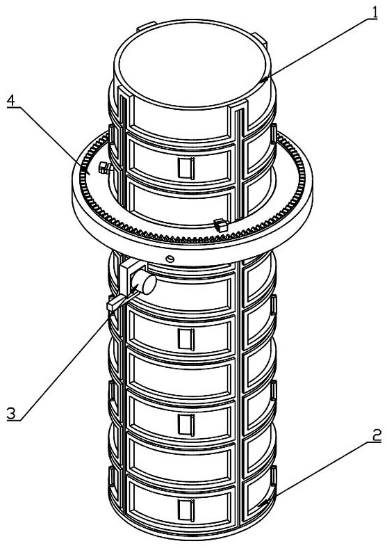
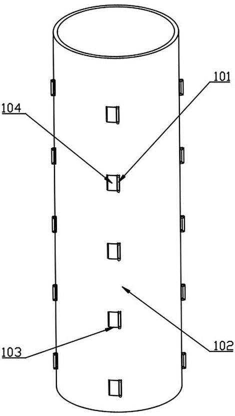
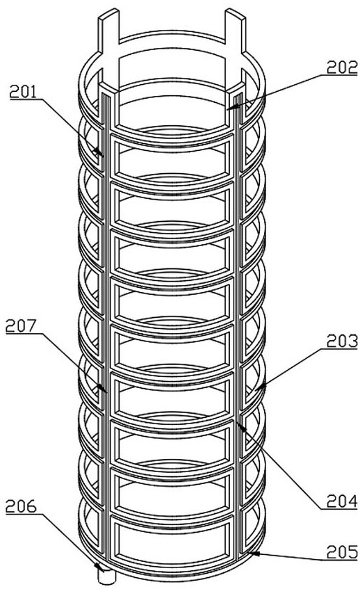
The invention provides concrete pouring equipment for a bridge pier column, belongs to the technical field of bridge construction, and aims to solve the problem of low efficiency during concrete pouring of an existing bridge pier column. The concrete pouring equipment comprises a fixing mechanism and a lifting mechanism, the fixing mechanism comprises a partition plate, the lifting mechanism comprises four supporting columns, the four supporting columns are fixed to the partition plate, lifting grooves are formed in the four supporting columns, a lifting screw rod and three sliding rods are rotationally arranged in the four lifting grooves, a lifting motor is fixed to the lower portion of one supporting column, an output shaft of the lifting motor is connected with the lifting screw rod, a plurality of supporting rings are fixed among the four supporting columns, annular grooves are formed in the supporting rings, a rotating mechanism is arranged on the lifting grooves in a sliding mode, and a knocking mechanism is arranged below the rotating mechanism. According to the concrete pouring equipment for the bridge pier column, the lifting mechanism, the knocking mechanism and the rotating mechanism are matched, concrete can be vibrated while being injected into the partition plate, and the concrete pouring efficiency of the bridge pier column is improved.

Description

technical field [0001] The invention belongs to the technical field of bridge construction and relates to concrete pouring equipment for bridge pier columns. Background technique [0002] Double-line bridges generally refer to bridges with two line tracks and the two line tracks are reversed. Double-line bridges are mostly viaducts. When laying viaducts, bridge piers are generally required to cross the terrain. General bridges When the pier column is poured, if the ordinary concrete is not vibrated in time after it is put into the mold, it cannot be compacted, which will easily lead to problems such as holes, exposed ribs, honeycomb, slag inclusions, etc., which will affect the bearing capacity and safety of the bridge pier column. Use and durability of buildings. [0003] The existing concrete pouring usually adopts segmental pouring. The steps are to inject a certain amount of concrete, put the vibrating device into it for vibrating, then remove the vibrating device, and ...

Claims


Application Information

Patent Timeline
Patent Type & Authority Applications(China)
IPC IPC(8): E01D21/00E01D19/02
CPCE01D21/00E01D19/02
Inventor 陈海李效全付静宇欧阳海漫肖坤李建堂赵延端
Owner SINOHYDRO ENG BUREAU 4
Learn More