Temperature sensor
A technology for temperature sensor and temperature detection, which is applied in thermometers, instruments, and thermometers based on the expansion/contraction of materials, etc., which can solve the problem of insufficient accuracy of temperature sensors
- Summary
- Abstract
- Description
- Claims
- Application Information
AI Technical Summary
Problems solved by technology
Method used
Image
Examples
Embodiment 1
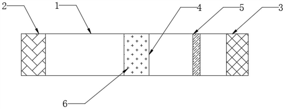
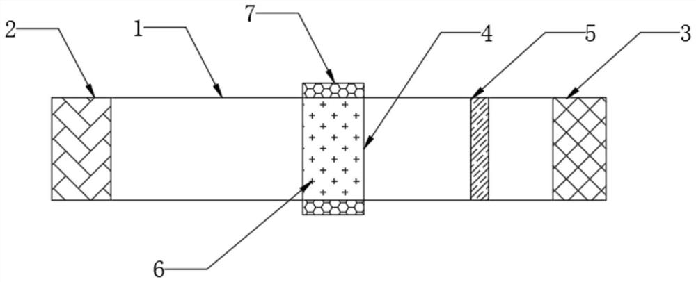
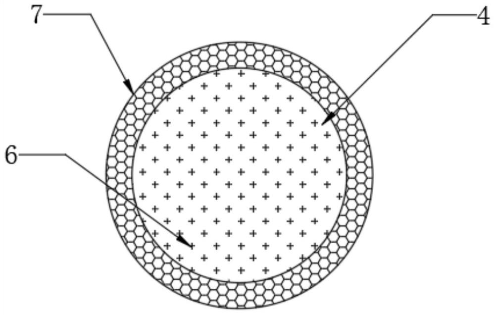
[0025] see figure 1 , figure 2 , Figure 4 , a temperature sensor, comprising an optical fiber 1, a laser 2 is arranged at one end of the optical fiber 1, a detector 3 is arranged at an end of the optical fiber 1 away from the laser 2, a thermal expansion part 4 is arranged at a middle position of the optical fiber 1, and a thermal expansion part 4 and the detector 3 are arranged A filter 5 is provided, a nanoparticle 6 is arranged in the thermal expansion part 4, a thermal contraction part 7 is provided on the outer wall of the thermal expansion part 4, a fixed part 8 is provided at both ends of the thermal expansion part 4, the thermal expansion part 4 is a transparent thermal expansion material, and the nanoparticle 6 It is NaYF4 doped with rare earth.
[0026] Specifically, when working, the laser 2 emits laser light, transmits and irradiates the thermal expansion part 4 through the optical fiber 1, and the nanocomposite material in the middle of the thermal expansion p...
Embodiment 2
[0031] On the basis of specific embodiment 1, please refer to figure 2 , image 3 Specifically, the heat shrinkable part 7 is connected to the outer wall of the heat expandable part 4 by sticking, and the material of the heat shrinkable part 7 is cross-linked polyethylene material. A circle of thermal contraction part 7 is arranged outside the thermal expansion part 4. When detecting the temperature, the thermal expansion part 4 is thermally expanded, and the thermal contraction part 7 is thermally contracted. The thermal contraction part 7 produces an inward pressure on the thermal expansion part 4, so that the thermal expansion part 4 Expanding to both sides, therefore, the thermal expansion part 4 will become longer, the concentration of nanoparticles 6 inside it will change more obviously, and the resulting light intensity will also change more obviously, which can effectively improve the detection accuracy and sensitivity.
Embodiment 3
[0033] On the basis of specific embodiment 1, special, please refer to Figure 4 , the shape of the fixing part 8 is wedge-shaped, and there are two fixing parts 8, which are distributed symmetrically at the top and bottom of the thermal expansion part 4 respectively. Wedge-shaped fixing parts 8 are provided at both ends of the thermal expansion part 4. When the thermal expansion part 4 expands in volume due to the influence of temperature, the upper and lower fixing parts 8 will generate forces in different directions on the thermal expansion part 4, so that the thermal expansion part 4 is twisted and the inside The change of the concentration of nanoparticles 6 is more obvious, so the change of the light intensity produced is more obvious, which can effectively improve the detection accuracy and sensitivity.
[0034] The relevant content of the temperature sensor is as described above, and will not be repeated here.
PUM
 Abstract
Description
Claims
Application Information
 - R&D
- Intellectual Property
- Life Sciences
- Materials
- Tech Scout
- Unparalleled Data Quality
- Higher Quality Content
- 60% Fewer Hallucinations
Browse by: Latest US Patents, China's latest patents, Technical Efficacy Thesaurus, Application Domain, Technology Topic, Popular Technical Reports.
© 2025 PatSnap. All rights reserved.Legal|Privacy policy|Modern Slavery Act Transparency Statement|Sitemap|About US| Contact US: help@patsnap.com


