Testing device for belt deviation test

A test device and deviation technology, which is applied in the direction of valve device, measuring device, mechanical parts test, etc., can solve the problems of manufacturer loss, belt skipping, tearing, and inability to reproduce stably, so as to achieve convenient operation and ensure service life Effect

Active Publication Date: 2021-09-07
DONGFENG LIUZHOU MOTOR
View PDF15 Cites 3 Cited by
  • Summary
  • Abstract
  • Description
  • Claims
  • Application Information

AI Technical Summary

Problems solved by technology

[0004] However, the deviation of the timing belt is caused by the verticality manufacturing tolerance of each pulley in the timing system, the flatness manufacturing tolerance of the pulley mounting surface, the lateral movement characteristics of the belt itself, and the action on each pulley after the belt is tensioned. Due to the combined effects of multiple factors such as the deformation of the timing belt, the direction of the timing belt deviation is unpredictable and cannot be reproduced stably
The simulation analysis software cannot simulate the deviation of the belt
[0005] Influenced by the life of the belt, various durability tests cannot verify whether the number of pulley ribs in the timing system and the design of the rib size can ensure that the side of the timing belt is not subject to abnormal wear
[0006] If there is abnormal wear on the side of the belt due to deviation during the operation of the belt, the belt will be worn narrower and narrower, which will eventually lead to failure modes such as belt skipping and tearing, which will affect the performance of the engine; in severe cases, the timing belt will break and the engine piston will Collision with the valve causes the engine to be scrapped
If the risk of early failure of the belt caused by partial wear of the belt cannot be effectively identified in the design and development stage, once bad products enter the market, it will bring huge losses to the manufacturer

Method used


Image

  • Testing device for belt deviation test
  • Testing device for belt deviation test
  • Testing device for belt deviation test

Examples


Embodiment Construction

[0026] The specific implementation manners of the present invention will be further described in detail below in conjunction with the accompanying drawings and embodiments. The following examples are used to illustrate the present invention, but are not intended to limit the scope of the present invention. Apparently, the described embodiments are only some of the embodiments of the present invention, but not all of them. Based on the embodiments of the present invention, all other embodiments obtained by persons of ordinary skill in the art without creative efforts fall within the protection scope of the present invention.

[0027] It should be understood that the terms "first", "second", etc. are used in the present invention to describe various information, but these information should not be limited to these terms, and these terms are only used to distinguish information of the same type from each other. For example, "first" information may also be referred to as "second"...


PUM


Abstract

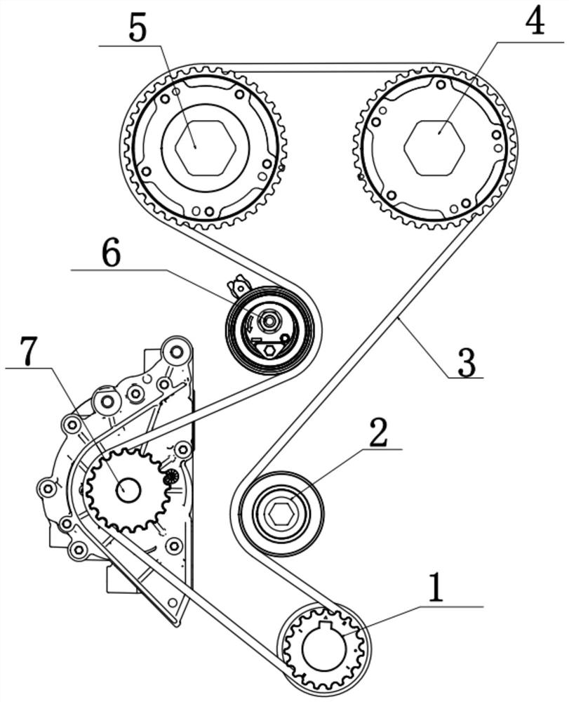
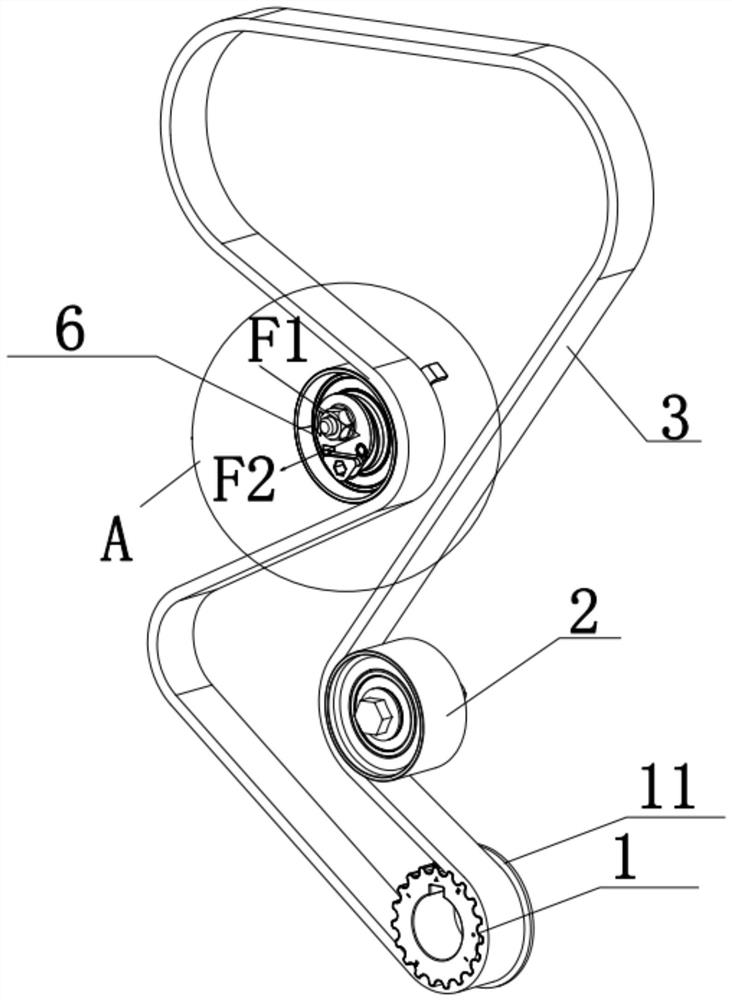
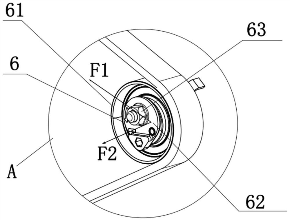
The invention relates to the technical field of belt detection, and discloses a testing device for a belt deviation test, which comprises a timing belt, and a crankshaft timing gear, a timing idle wheel, an intake camshaft gear, an exhaust camshaft gear and a timing tensioning wheel connected with the timing belt in a winding manner. The crankshaft timing gear is connected with an output shaft of an engine; the exhaust camshaft gear and the intake camshaft gear are positioned in the same horizontal plane; the timing tensioning wheel is located below the exhaust cam shaft gear; the crankshaft timing gear, the timing idle wheel, the intake camshaft gear and the exhaust camshaft gear are installed in the same vertical plane, an included angle alpha is formed between the axis of the timing tensioning wheel and the horizontal plane, a sensor used for detecting the deviation force of the timing belt is arranged on the crankshaft timing gear, and the deviation force of the timing belt is changed by adjusting the angle alpha. According to the technical scheme, the testing device for the belt deviation test can better meet the actual use condition of the timing belt, so that what is ensured is that the service life of the timing belt is reasonable, and failure of the timing belt is avoided.

Description

technical field [0001] The invention relates to the technical field of belt detection, in particular to a test device for a belt deviation test. Background technique [0002] Timing belt drive has the advantages of low noise, accurate transmission ratio, smooth operation, and no need for lubrication. It has been widely used in the timing system of engines with overhead camshafts. The engine timing belt transmission system includes the intake and exhaust camshaft gears, timing tensioner, water pump, crankshaft timing gear, timing idler pulley and timing belt. The timing belt is a rubber part, which is a weak link in the timing transmission system. Its failure modes mainly include the whole belt breaking, tooth breaking, tooth surface wear and belt side wear. [0003] At present, in the design and development process of the timing belt transmission system, through various engine analysis software such as AVL-ETD, the dynamic simulation calculation of the timing belt transmiss...

Claims


Application Information

Patent Timeline
Patent Type & Authority Applications(China)
IPC IPC(8): G01M13/023G01M13/026F01L1/348
CPCG01M13/023G01M13/026F01L1/348
Inventor 江申达何道明潘永亮姚克甫马百坦邓发平
Owner DONGFENG LIUZHOU MOTOR
Why Eureka
Try Eureka