Radio frequency transceiving front end

A radio frequency transceiver and transmitter technology, applied in the field of radio frequency transceiver front-end, can solve the problems of unfavorable portability of communication equipment, use of quality-sensitive equipment, and large layout area.

Active Publication Date: 2021-09-07
深圳市时代速信科技有限公司
View PDF9 Cites 0 Cited by
  • Summary
  • Abstract
  • Description
  • Claims
  • Application Information

AI Technical Summary

Problems solved by technology

[0004]However, the existing technology still has the following disadvantages: 1. Due to the influence of the circulator, the area and quality of the existing RF front-end are often too large, which is not conducive to the communication equipment

Method used


Image

  • Radio frequency transceiving front end
  • Radio frequency transceiving front end
  • Radio frequency transceiving front end

Examples


specific Embodiment 1

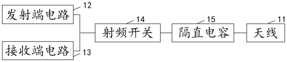
[0026] This embodiment provides a radio frequency transceiver front end 1 . figure 1 A circuit diagram of an embodiment of a radio frequency transceiver front end according to the present invention is shown. image 3 A structural diagram of an embodiment of a radio frequency transceiver front end according to the present invention is shown. Such as figure 1 and image 3 As shown, the radio frequency transceiver front end 1 includes an antenna 11 , a transmitter circuit 12 , a receiver circuit 13 , a radio frequency switch 14 and a DC blocking capacitor 15 .

[0027] Specifically, the transmitting end circuit 12 includes a power amplifier 121 and a first DC blocking capacitor 122 , and the receiving end circuit 13 includes a low noise amplifier 131 and a second DC blocking capacitor 132 . Wherein, the power amplifier 121 is composed of a first input matching network, a first transistor and a first output matching network, and the low noise amplifier 131 is composed of a seco...

specific Embodiment 2

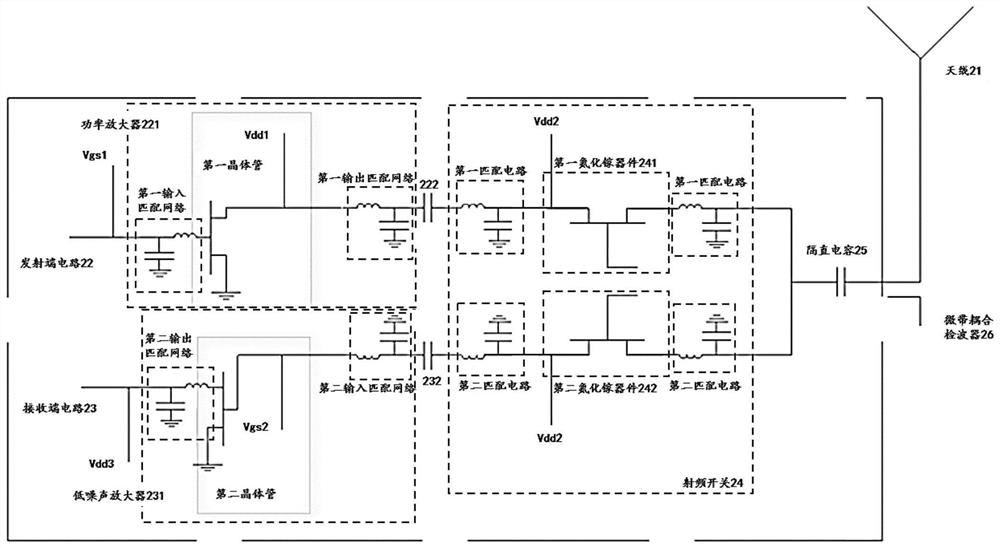
[0039] This embodiment provides a radio frequency transceiver front end 2 . figure 2 A circuit diagram of another embodiment of a radio frequency transceiver front end according to the present invention is shown. As shown in the figure, the radio frequency transceiver front end 2 includes an antenna 21 , a transmitter circuit 22 , a receiver circuit 23 , a radio frequency switch 24 and a DC blocking capacitor 25 .

[0040] Specifically, the transmitting end circuit 22 includes a power amplifier 221 and a first DC blocking capacitor 222 , and the receiving end circuit 23 includes a low noise amplifier 231 and a second DC blocking capacitor 232 . Wherein, the power amplifier 221 is composed of a first input matching network, a first transistor and a first output matching network, and the low noise amplifier 231 is composed of a second input matching network, a second transistor and a second output matching network. The radio frequency switch 24 is respectively connected to the...


PUM


Abstract

The invention provides a radio frequency transceiving front end, and the front end comprises an antenna, a transmitting end circuit, a receiving end circuit, a radio frequency switch and a blocking capacitor; the radio frequency switch is connected to the transmitting end circuit and the receiving end circuit, the antenna is connected to two ends of the radio frequency switch through the blocking capacitor, the transmitting end circuit is used for amplifying the power of a radio frequency signal to be transmitted, the receiving end circuit is used for reducing the noise interference of the system and amplifying the received radio frequency signal, and the transmitting end circuit and the receiving end circuit are integrated in a package. The radio frequency switch is connected in series with the transmitting end circuit of the radio frequency transceiving front end, and the transmitting end circuit and the receiving end circuit are integrated together, so that the size of the radio frequency transceiving front end is obviously reduced, and the portability and wide applicability of the radio frequency transceiving front end are improved.

Description

technical field [0001] The invention relates to the field of radio frequency transceiver, in particular to a radio frequency transceiver front end. Background technique [0002] Wireless communication has brought great convenience to human communication and control communication. Wireless communication includes various fixed, mobile and portable applications, such as two-way radios, mobile phones, personal digital assistants and wireless networks. Examples of other radio wireless communication include GPS, garage door remotes, wireless mice, etc. In the era of rapid development of wireless communication technology, the miniaturization of communication system is an important research direction. [0003] In the prior art, a high-power TDD radio frequency system uses a combination of a circulator and a switch to implement transceiver isolation and transmit standing wave protection. Because the high-power RF switch is not easy to realize, the RF switch is often placed at the r...

Claims


Application Information

Patent Timeline
IPC IPC(8): H04B1/40
CPCH04B1/40
Inventor 刘石头杨天应张胜峰
Owner 深圳市时代速信科技有限公司
Why Eureka
Try Eureka