
Universal fixture for flat plate type parts subjected to milling

A flat plate and fixture technology, applied in metal processing mechanical parts, clamping, manufacturing tools, etc., can solve the problems of workpiece flying out of the vise, difficult to control flatness, and difficult to ensure flatness requirements.

Active Publication Date: 2021-09-10
AEROSPACE PRECISION PROD INC LTD
View PDF9 Cites 0 Cited by
  • Summary
  • Abstract
  • Description
  • Claims
  • Application Information

AI Technical Summary

Problems solved by technology

If the size of the plate is larger than 300mm, it cannot be clamped. Even if the size is less than 300mm, for example, the plate with a thickness of 200*200*10 is processed, it is difficult to guarantee the flatness requirements when clamping with a vise.
The strength of the clamping vise determines the clamping force of the workpiece. If the clamping force is too large, the middle part of the workpiece will be deformed due to clamping, and the middle part of the bottom surface can be supported by pad iron on both sides after the vise is clamped. Without support, large vibrations will be generated during milling, which will affect the surface roughness of the workpiece. Since the plane will definitely rebound after being deformed during clamping and loosening, the flatness requirements cannot be guaranteed.
If the clamping force is too small, the workpiece will not be deformed, but the workpiece may fly out of the vise due to the cutting force of the tool during processing, causing danger;
[0004] 2. Clamping with a press plate: When using a press plate to mill the plate, the incoming plane of the plate blank to be processed is usually not flat. If you directly use the press plate to press the four points of the blank, the position of the pressure point will fluctuate, resulting in When the pressing plate is clamped, it is affected by external force, which will cause distortion and deformation of the plane at other positions of the workpiece. After pressing the plate, it is difficult to level the plane due to two processings, and it is also difficult to control the flatness after processing;
[0005] 3. Vacuum suction cup clamping: Vacuum suction cup clamping is only suitable for flat workpieces without milled cavities or holes in the middle. If there are many through holes or through cavities in the middle of flat workpieces at different positions, then Cannot be clamped with vacuum suction cups

Method used


Image

  • Universal fixture for flat plate type parts subjected to milling
  • Universal fixture for flat plate type parts subjected to milling
  • Universal fixture for flat plate type parts subjected to milling

Examples


Embodiment Construction

[0030] It should be noted that, in the case of no conflict, the embodiments of the present invention and the features in the embodiments can be combined with each other.

[0031] In describing the present invention, it should be understood that the terms "center", "longitudinal", "transverse", "upper", "lower", "front", "rear", "left", "right", " The orientations or positional relationships indicated by "vertical", "horizontal", "top", "bottom", "inner" and "outer" are based on the orientations or positional relationships shown in the drawings, and are only for the convenience of describing the present invention and Simplified descriptions, rather than indicating or implying that the device or element referred to must have a particular orientation, be constructed and operate in a particular orientation, and thus should not be construed as limiting the invention. In addition, the terms "first", "second", etc. are used for descriptive purposes only, and should not be understood ...


PUM


Abstract

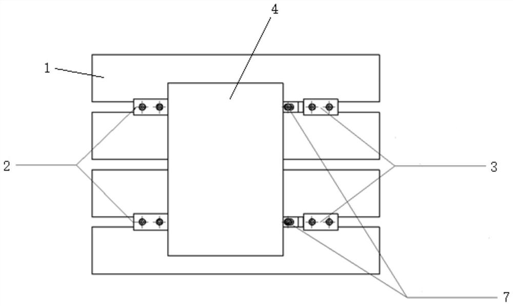
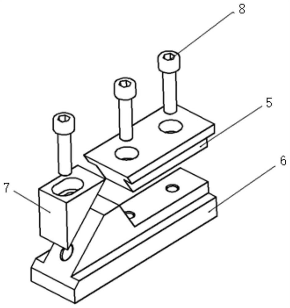
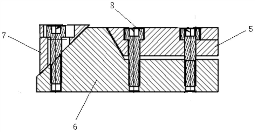
The invention provides a universal fixture for flat plate type parts subjected to milling. The universal fixture for the flat plate type parts subjected to milling comprises positioning assemblies and locking assemblies, wherein the positioning assemblies and the locking assemblies are detachably connected with a machine tool workbench; and the positioning assemblies and the locking assemblies are arranged on the two sides of the parts in a one-to-one correspondence mode and abut against the side walls of the parts respectively. When the fixture provided by the invention is in use, a workpiece only needs to be flatly laid on the workbench, the positioning assemblies abut against one side of the workpiece, the locking assemblies and the workbench are locked on the other side of the workpiece, then bolts are slowly tightened to enable sliding locking blocks to abut against the other side of the workpiece, and the workpiece is locked in a side pressing mode through a small contact face; the workpiece is directly placed on the workbench, so that the bottom face of the workpiece has a good supporting effect during machining, and cutter vibration is not prone to being generated; downward pressing force does not exist, so that deformation caused by external force due to the fact that clamping force is too large or the surface of a blank is uneven can be avoided; and the requirement for the appearance and the surface of the workpiece is low due to the fact that the clamping position is adjustable, so that clamping can be conducted even if the two side faces are not parallel, and the applicability is high.

Description

technical field [0001] The invention belongs to the field of numerical control processing equipment, and in particular relates to a universal fixture for milling flat plate parts. Background technique [0002] The type of parts processed by the machining center often encounters the processing of large-sized thin plate parts, and there are often workpieces that have strict geometric tolerance requirements for flatness due to assembly requirements, and machining centers need to be used to mill flat workpieces. The commonly used clamping methods for milling plate parts in machining centers mainly include the following three types: [0003] 1. Vise clamping and clamping: Taking the 850-stroke machining center as an example, the maximum opening and closing size of the vise is usually about 300mm. If the size of the plate is larger than 300mm, it cannot be clamped. Even if the size is less than 300mm, for example, the plate with the outer dimension of 200*200*10 thick is processe...

Claims


Application Information

Patent Timeline
Patent Type & Authority Applications(China)
IPC IPC(8): B23Q3/06
CPCB23Q3/062
Inventor 李彦杰张亚晓王博洋
Owner AEROSPACE PRECISION PROD INC LTD
Learn More