Pneumatic reverse thrust type undercarriage for unmanned aerial vehicle and use method of pneumatic reverse thrust type undercarriage
A drone and landing gear technology, applied in the field of drones, can solve the problems of unprotected landing gear, increased inertia of drones, and poor functionality.
- Summary
- Abstract
- Description
- Claims
- Application Information
AI Technical Summary
Problems solved by technology
Method used
Image
Examples
Embodiment 1
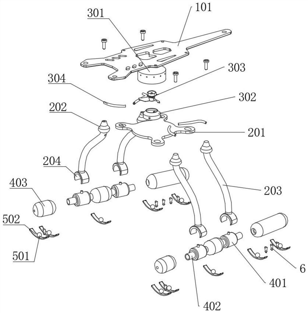
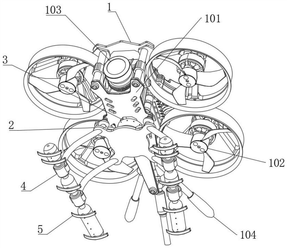
[0059] see Figure 1-13 , a pneumatic reverse thrust landing gear for unmanned aerial vehicles, including a load-bearing base plate 101 fixedly installed on the lower end of the unmanned aerial vehicle body 1, a plurality of driving structures 102 are installed on the upper end of the load-bearing base plate 101, and a visual structure 103 is installed on the front end of the load-bearing base plate 101 An empennage structure 104 is installed at the rear end of the load-bearing base plate 101, and a set of reverse thrust landing gear assemblies 2 are connected to the left and right ends of the load-bearing base plate 101. Between the two sets of reverse thrust landing gear assemblies 2, the lower end of the reverse thrust landing gear assemblies 2 is connected with a pneumatic reverse thrust buffer assembly 4, and the air-inflated reverse thrust assembly 3 communicates with the pneumatic reverse thrust cushion assembly 4 through the reverse thrust landing gear assembly 2. conn...
Embodiment 2
[0067] see Figure 1-13 , where the same or corresponding components as those in Embodiment 1 use the corresponding reference numerals as in Embodiment 1, and for the sake of simplicity, only the differences from Embodiment 1 will be described below. The difference between this embodiment 2 and embodiment 1 is: please refer to figure 1 and Figure 10-12 , the air pressure expander 6 is fixedly installed in the anti-thrust air hole, the air pressure expander 6 includes a conical air intake pipe 601, the upper end of the conical air intake pipe 601 is connected with the rubber buffer post 403, and the lower end of the conical air intake pipe 601 is fixedly connected with a peach The lower end of the peach-shaped pressurizing tube 602 is fixedly connected with a pressurized air outlet pipe 603, and the lower end of the pressurized air outlet pipe 603 extends to the outside of the rubber buffer post 403. By installing the air pressure expander 6 in the reverse thrust air hole, t...
Embodiment 3
[0071] see Figure 1-13 , where the same or corresponding components as those in Embodiment 1 use the corresponding reference numerals as in Embodiment 1, and for the sake of simplicity, only the differences from Embodiment 1 will be described below. The difference between this embodiment 3 and embodiment 1 is: please refer to figure 1 and Figure 10 The lower end of the rubber buffer column 403 is connected with a plurality of horizontal balance assemblies 5, and the horizontal balance assembly 5 includes a balance ball head 501. The lower end of the rubber buffer column 403 is provided with a plurality of ball grooves, and the ball grooves are rotationally connected with balance ball heads 501. The lower end of the ball head 501 is fixedly connected with an arc balance plate 502 through a connecting rod, and the inner arc diameter of the arc balance plate 502 is at least 3 times of the outer diameter of the rubber buffer column 403 . By setting the horizontal balance compo...
PUM
 Abstract
Description
Claims
Application Information
 - R&D
- Intellectual Property
- Life Sciences
- Materials
- Tech Scout
- Unparalleled Data Quality
- Higher Quality Content
- 60% Fewer Hallucinations
Browse by: Latest US Patents, China's latest patents, Technical Efficacy Thesaurus, Application Domain, Technology Topic, Popular Technical Reports.
© 2025 PatSnap. All rights reserved.Legal|Privacy policy|Modern Slavery Act Transparency Statement|Sitemap|About US| Contact US: help@patsnap.com


