
Light path system, monocular three-dimensional image acquisition system and three-dimensional strain detection system

A technology of optical path system and acquisition system, which is applied in the field of measurement technology and 3D vision, and can solve problems such as inability to meet the requirements of 3D data measurement, uneven brightness, and missing data.

Pending Publication Date: 2021-09-10
深圳市海塞姆科技有限公司
View PDF8 Cites 2 Cited by
  • Summary
  • Abstract
  • Description
  • Claims
  • Application Information

AI Technical Summary

Problems solved by technology

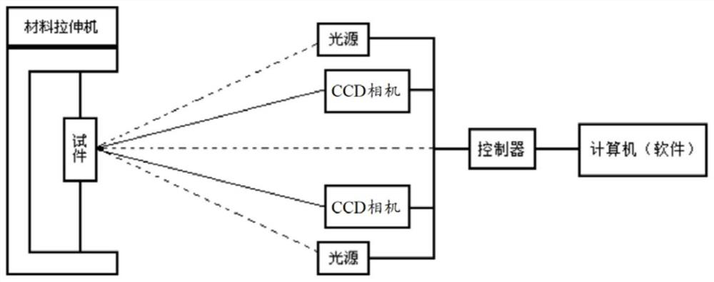
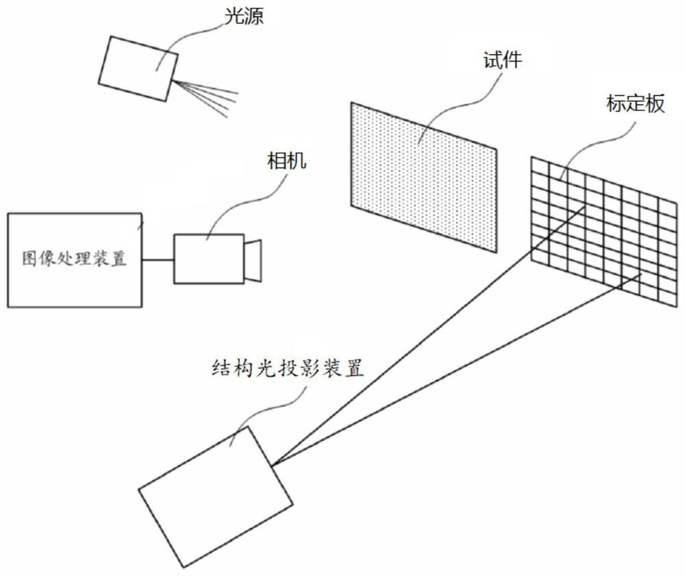
[0007] For example, Patent Document 2 discloses a method of using a two-dimensional extensometer based on structured light, such as figure 2 As shown, it uses a single camera and lens to collect images for processing and analysis. It can only measure the strain in the two-dimensional direction and cannot meet the measurement requirements of three-dimensional data.
Moreover, the light source is arranged on the left side of the camera and lens. When the measurement process requires a short exposure time, the brightness on the left and right sides of the sample will be uneven, resulting in data loss in the darker parts.
[0008] Therefore, in the prior art, there is no relevant optical path scheme that can be used with the monocular 3D DIC algorithm for 3D strain measurement. Therefore, there is an urgent need for a new optical path system that can be based on the 3D DIC algorithm and can be used for 3D strain detection.

Method used


Image

  • Light path system, monocular three-dimensional image acquisition system and three-dimensional strain detection system
  • Light path system, monocular three-dimensional image acquisition system and three-dimensional strain detection system
  • Light path system, monocular three-dimensional image acquisition system and three-dimensional strain detection system

Examples


Embodiment Construction

[0041] Embodiments of the present application will be described in detail below in conjunction with the accompanying drawings.

[0042] Embodiments of the present application are described below through specific examples, and those skilled in the art can easily understand other advantages and effects of the present application from the content disclosed in this specification. Apparently, the described embodiments are only some of the embodiments of this application, not all of them. The present application can also be implemented or applied through other different specific implementation modes, and various modifications or changes can be made to the details in this specification based on different viewpoints and applications without departing from the spirit of the present application. It should be noted that, in the case of no conflict, the following embodiments and features in the embodiments can be combined with each other. Based on the embodiments in this application, all...


PUM


Abstract

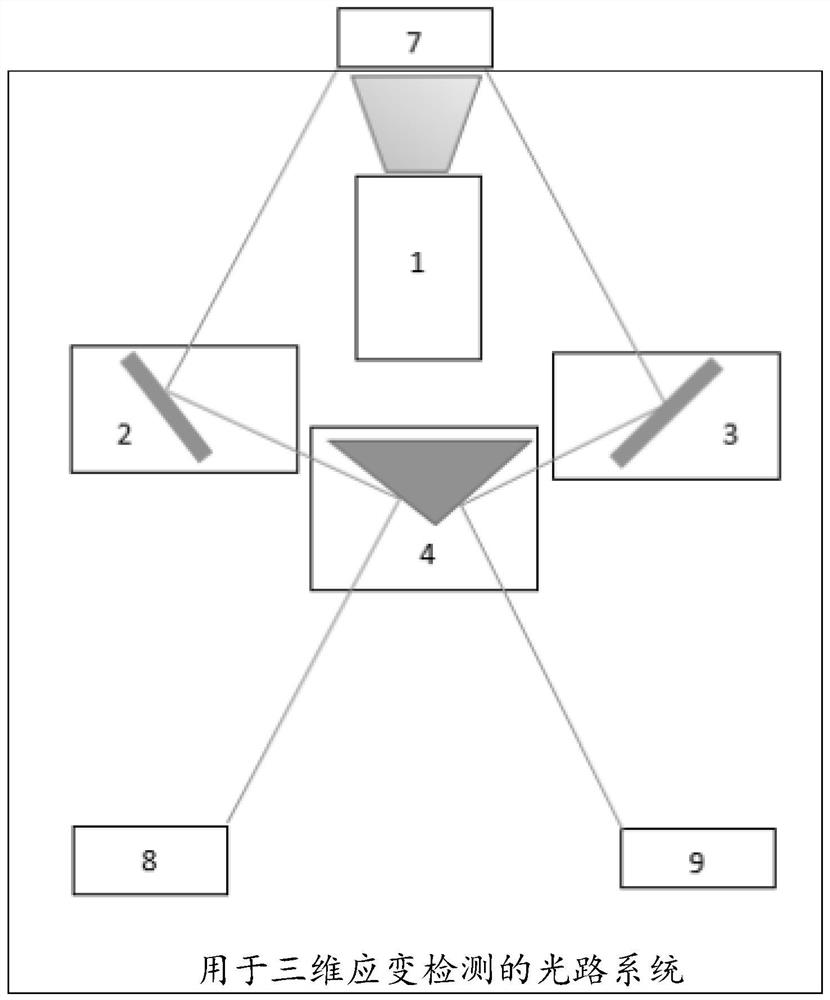
The embodiment of the invention provides a light path system for three-dimensional strain detection, a monocular three-dimensional image acquisition system and a three-dimensional strain detection system, belongs to the technical field of measurement technology and three-dimensional vision, and is specifically characterized in that a light source is arranged in front of a triangular prism and emits light so as to generate reflection light on the surface of a tested sample; a first reflective mirror is arranged on one side of the light source and reflects the reflected light to the first mirror surface of the triangular prism to form a first virtual image; and a second reflective mirror is arranged on the other side of the light source and reflects the reflected light to the second mirror surface of the triangular prism to form a second virtual image. Through the processing scheme of the invention, an optical path system in three-dimensional strain measurement based on a three-dimensional DIC algorithm can be simplified, the structure of the three-dimensional strain detection system is simplified, and the detection efficiency is improved.

Description

technical field [0001] This specification relates to the fields of measurement technology and three-dimensional vision technology, and specifically relates to an optical path system for three-dimensional strain detection, a monocular three-dimensional image acquisition system and a three-dimensional strain detection system. Background technique [0002] At present, the detection of deformation in mechanical properties has been very popular. The detection of deformation can be applied to the strain test of various materials and structures. sex. Therefore, how to detect deformation accurately and efficiently becomes more and more important. [0003] At present, in deformation detection, the traditional optical system based on DIC technology (Digital Image Correlation, also known as digital speckle correlation method) generally has the following two schemes: [0004] The first is an optical path system that uses a binocular image acquisition device and a binocular 3D DIC algo...

Claims


Application Information

Patent Timeline
IPC IPC(8): G01B11/16G02B26/08
CPCG01B11/16G02B26/0816G02B26/0883
Inventor 李长太
Owner 深圳市海塞姆科技有限公司
Learn More