Air inlet simulation system, air inlet simulation method and empty model pressure loss simulation method

A technology for simulating systems and models, applied in the field of wind tunnel testing, which can solve problems such as poor flow stability, large pressure loss range, and insufficient suction capacity.

Active Publication Date: 2021-09-10
LOW SPEED AERODYNAMIC INST OF CHINESE AERODYNAMIC RES & DEV CENT
View PDF16 Cites 5 Cited by
  • Summary
  • Abstract
  • Description
  • Claims
  • Application Information

AI Technical Summary

Problems solved by technology

[0005] 1. In the prior art, the internal structure of the engine models of different types of aircraft is quite different, resulting in a large change in the pressure at the inlet end of the intake simulation pipeline, and a large range of pressure loss;
[0006] 2. If a large-diameter pipe is used in the air intake simulation, there will be problems of small suction volume, poor flow stability and inaccurate flow measurement under the conditions of small pressure loss and low flow air intake;
[0007] If a small-diameter pipe is used in the intake simulation, the suction capacity is seriously insufficient, and it is difficult to meet the intake conditions of large pressure loss and small flow

Method used


Image

  • Air inlet simulation system, air inlet simulation method and empty model pressure loss simulation method
  • Air inlet simulation system, air inlet simulation method and empty model pressure loss simulation method
  • Air inlet simulation system, air inlet simulation method and empty model pressure loss simulation method

Examples


Embodiment 1

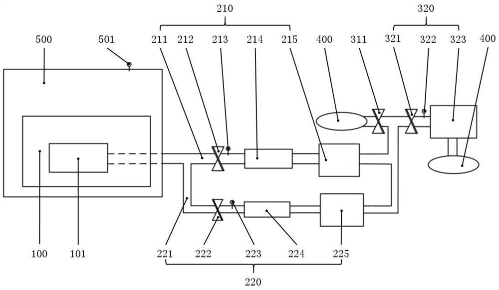
[0046] Such as figure 1 As shown, Embodiment 1 of the present invention provides an air intake simulation system, including: a test model 100, a large-flow air extraction mechanism 210, a small-flow air extraction mechanism 220, and an air outlet mechanism (not shown in the figure due to the viewing angle) ):

[0047] The inlet end of the small-flow air extraction mechanism 220, the air inlet end of the large-flow air extraction mechanism 210, and the air outlet end of the test model 100 are connected to each other;

[0048] The large flow suction mechanism 210 includes a large centrifugal fan 215, and the large centrifugal fan 215 is located on the large flow suction mechanism 210 and is close to the gas outlet side, and the small flow suction mechanism 220 includes a small centrifugal fan 225. The small centrifugal fan 225 is located on the side of the small flow suction mechanism 220 close to the air outlet, and the flow rate of the large centrifugal fan 215 is greater tha...

Embodiment 2

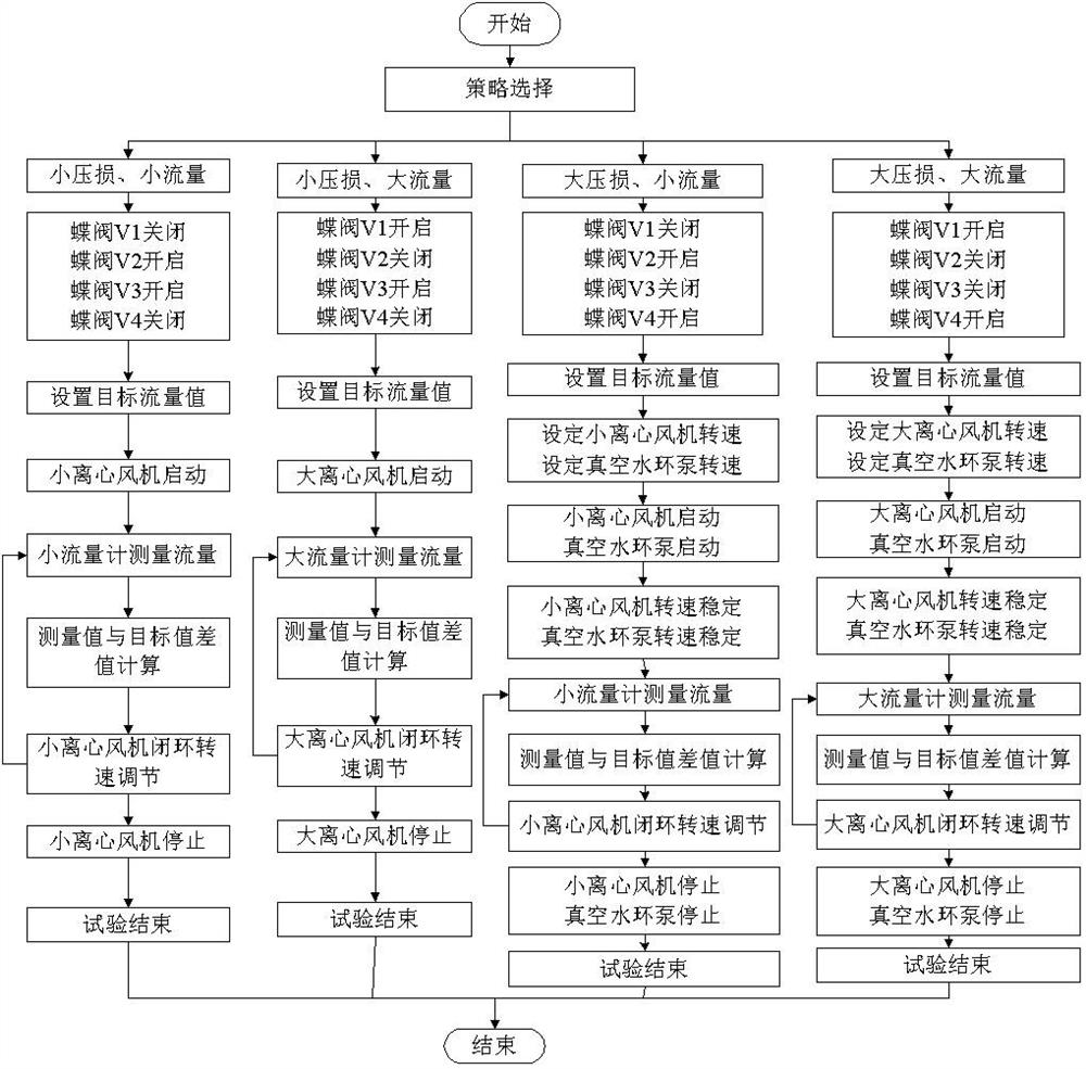
[0067] Such as figure 2 As shown, Embodiment 2 of the present invention provides an air intake simulation method of an air intake simulation system, which is characterized in that it includes the following steps:

[0068] Obtaining test requirements, the test requirements include pressure loss requirements and flow requirements, the pressure loss requirements include large pressure loss or small pressure loss, and the flow requirements include large flow or small flow;

[0069] When the pressure loss demand is a large pressure loss, then close the third on-off valve 311, open the fourth on-off valve 321 and the vacuum pump 323; when the pressure loss demand is a small pressure loss, then open the The third on-off valve 311 closes the fourth on-off valve 321;

[0070] When the flow demand is a small flow, then open the large flow pumping mechanism 210, close the small flow pumping mechanism 220; when the flow demand is small flow, then open the small flow pumping mechanism 22...

Embodiment 3

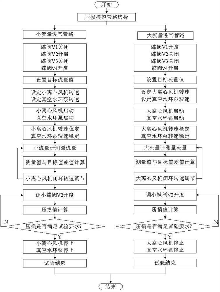
[0080] Such as image 3 As shown, Embodiment 3 of the present invention provides a schematic diagram of the air intake simulation system in Embodiment 1 in the air model pressure loss simulation. A method for simulating air model pressure loss of an air intake simulation system, comprising the steps of:

[0081] When performing large-flow empty model pressure loss simulation, open the large-flow pumping mechanism 210 and the fourth switching valve 321, and adjust the opening of the large-flow pumping mechanism 210 to obtain the first pressure at different openings Pressure value of sensor 501 P 1 and the pressure value of the second pressure sensor 213 P 2 , to calculate the pressure loss value of the large flow rate P s 2 for: P s 2 =P 1 -P 3 ; When carrying out the small-flow empty model pressure loss simulation, open the small-flow pumping mechanism 220 and the fourth switching valve 321, and adjust the opening of the small-flow pumping mechanism 220 to obtain...


PUM


Abstract

The invention is suitable for the technical field of wind tunnel tests, and provides an air inlet simulation system, an air inlet simulation method and an empty model pressure loss simulation method, and the system comprises a test model, a large-flow air exhaust mechanism, a small-flow air exhaust mechanism and an air outlet mechanism. The system is characterized in that the air inlet end of the small-flow air exhaust mechanism, the air inlet end of the large-flow air exhaust mechanism and the air outlet end of the test model are communicated with one another; the large-flow air exhaust mechanism comprises a large centrifugal fan, the large centrifugal fan is located on the side, close to the air outlet end, of the large-flow air exhaust mechanism, and the small centrifugal fan is located on the side, close to the air outlet end, of the small-flow air exhaust mechanism; and the air inlet end of the air outlet mechanism is communicated with the air outlet ends of the large-flow air exhaust mechanism and the small-flow air exhaust mechanism. The invention aims to provide an air inlet simulation system suitable for different types of engine models, can meet various air inlet simulation requirements, and has the characteristics of wide flow range, stable flow and the like.

Description

technical field [0001] The invention belongs to the technical field of wind tunnel tests, and in particular relates to an air intake simulation system, an air intake simulation method and an air model pressure loss simulation method. Background technique [0002] Aircraft icing is a more noticeable source of danger in flight safety accidents. The icing on the surface of the aircraft destroys the aerodynamic shape of the aircraft, leading to a decrease in aerodynamic characteristics, and the relative amount of icing on different parts of the aircraft has different effects on the flight. Even There is a small amount of icing, but if the small amount of icing occurs in a critical position, the degree of harm is the same as that of a large area of ​​icing in other positions. Therefore, the study of icing on different parts of the aircraft has become an important issue that needs to be solved urgently. Among them, when the aircraft engine is running, a large amount of air is inha...

Claims


Application Information

Patent Timeline
Patent Type & Authority Applications(China)
IPC IPC(8): G01M9/02G01M9/08G01M15/00
CPCG01M9/02G01M9/08G01M15/00Y02T90/00
Inventor 冉林熊建军王梓旭易贤赵照
Owner LOW SPEED AERODYNAMIC INST OF CHINESE AERODYNAMIC RES & DEV CENT
Why Eureka
Try Eureka