
Multi-station multifunctional machining lathe

A mechanical processing and multi-functional technology, applied in the direction of metal processing machinery parts, metal processing equipment, turning equipment, etc., can solve the problems of single function and low work efficiency

Pending Publication Date: 2021-09-14
CHANGDE LIANJIA MACHINERY
View PDF0 Cites 1 Cited by
  • Summary
  • Abstract
  • Description
  • Claims
  • Application Information

AI Technical Summary

Problems solved by technology

[0002] Machining is the process of changing the shape or performance of workpieces through mechanical equipment. In the machining industry, lathes are one of the most widely used mechanical equipment. Turning tools, drills, reamers, reamers, taps, dies and knurling tools to turn rotating workpieces; however, the existing lathes only have a single function and can only process one workpiece at a time, resulting in low work efficiency. Therefore, a lathe with multiple functions that can process multiple workpieces at the same time is required lathe

Method used


Image

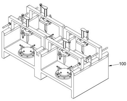
  • Multi-station multifunctional machining lathe
  • Multi-station multifunctional machining lathe
  • Multi-station multifunctional machining lathe

Examples


Embodiment 1

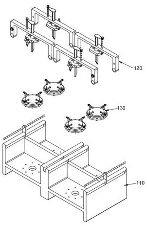
[0034] see Figure 1-Figure 6 As shown, the purpose of this embodiment is to provide a multi-station multifunctional machining lathe, including a processing bed 100, and the processing bed 100 at least includes:

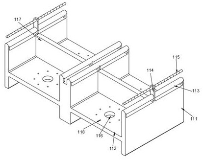
[0035] Placement body 110, placement body 110 comprises processing table 111, and processing table 111 is " H " type structure, and processing table 111 upper surface is provided with a plurality of processing chambers 112, and the top of processing table 111 is provided with slide shaft 113, and processing chamber 112 tops A power slot 116 is provided, and the power slot 116 is a cylindrical structure groove, and a fixed body 130 is arranged in the power slot 116;

[0036] The processing body 120, the processing body 120 includes a suspension 121, the suspension 121 is a "C"-shaped structure, the bottoms of both ends of the suspension 121 are provided with sliding openings 122 penetrating the surface, the sliding openings 122 are circular openings, sliding A slidin...

Embodiment 2

[0045] see Figure 7-Figure 9 As shown, while realizing simultaneous processing of multiple workpieces and having multiple processing capabilities, the fixation of the workpieces is ensured, and the following improvements are made on the basis of Embodiment 1:

[0046] Wherein, the fixed body 130 comprises a fixed disk 131 and a shielding body 132, the shielding body 132 comprises a shielding cover 138, the fixed disk 131 comprises a servomotor 133 positioned in the power slot 116, the top of the servomotor 133 is connected with a rotating disk 134 for rotation, and the rotating disk 134 The side is provided with a plurality of size connectors 135, the top of the size connector 135 is provided with a size thread groove 1351 that runs through its surface, the size thread groove 1351 is internally threaded with a size threaded rod 136, and one end of the size threaded rod 136 is provided with a contact body 1361 , by being provided with the size thread groove 1351, the size thre...


PUM


Abstract

The invention discloses a multi-station multifunctional machining lathe. The multi-station multifunctional machining lathe comprises a machining bed, the machining bed at least comprises a placing body and a machining body, the placing body comprises a machining table, the machining table is provided with a plurality of machining bins, the machining table is provided with a sliding shaft, the machining bins are provided with power grooves, and the power grooves are provided with fixing bodies; and the machining body comprises a suspension, the suspension is provided with a sliding opening and a lifting groove, the lifting groove is connected with a cutting body, the cutting body comprises a middle connecting body, the middle connecting body is provided with a mounting opening, and the mounting opening is connected with a turning tool. According to the multi-station multifunctional machining lathe, a plurality of workpieces can be treated at the same time, various machining capacities are achieved, and the machining efficiency of the workpieces is improved.

Description

technical field [0001] The invention relates to the technical field of mechanical processing, in particular to a multi-station multifunctional machining lathe. Background technique [0002] Machining is the process of changing the shape or performance of workpieces through mechanical equipment. In the machining industry, lathes are one of the most widely used mechanical equipment. Turning tools, drills, reamers, reamers, taps, dies and knurling tools to turn rotating workpieces; however, the existing lathes only have a single function and can only process one workpiece at a time, resulting in low work efficiency. Therefore, a lathe with multiple functions that can process multiple workpieces at the same time is required lathe. Contents of the invention [0003] The object of the present invention is to provide a multi-station multifunctional machining lathe to solve the problems raised in the background technology above. [0004] In order to achieve the above object, the...

Claims


Application Information

Patent Timeline
Patent Type & Authority Applications(China)
IPC IPC(8): B23B3/06B23Q11/08B23Q11/10
CPCB23B3/06B23Q11/08B23Q11/10
Inventor 王建忠刘雪平王勇
Owner CHANGDE LIANJIA MACHINERY
Learn More