Crawling ladder welding device based on ground rail robot

A welding device and robot technology, used in auxiliary devices, welding equipment, engine lubrication, etc., can solve problems such as lubricating oil easily contaminated with dust, increasing cleaning difficulty, bending deformation at both ends of L-shaped crossbar, etc.

Inactive Publication Date: 2021-09-14
孙瑞琴
View PDF0 Cites 0 Cited by
  • Summary
  • Abstract
  • Description
  • Claims
  • Application Information

AI Technical Summary

Problems solved by technology

[0005] In order to overcome the welding operation of the existing device, due to the small contact area between the two ends of the L-shaped cross bar and the two vertical bars, the structural stability of the ladder after welding is poor, and at the same time, the two ends of some L-shaped cross bars will be bent The deformation phenomenon leads to insufficient contact between the two ends of the L-shaped cross bar and the two vertical bars, which seriously affects the welding operation. In addition, the existing device cannot make multiple sets of L-shaped cross bars perpendicular to the vertical bars at the same time, so that some of the cross bars appear after welding. Skew phenomenon, in addition, when the existing device uses the ground rail robot for welding, it is necessary to manually add lubricating oil to the guide rail at regular intervals, which is inefficient. At the same time, the lubricating oil will drip into the device during use, and the lubricating oil is extremely It is easy to be contaminated with dust, which greatly increases the difficulty of cleaning. The technical problem to be solved is: to provide a ladder welding device based on the ground rail robot

Method used


Image

  • Crawling ladder welding device based on ground rail robot
  • Crawling ladder welding device based on ground rail robot
  • Crawling ladder welding device based on ground rail robot

Examples


Embodiment 1

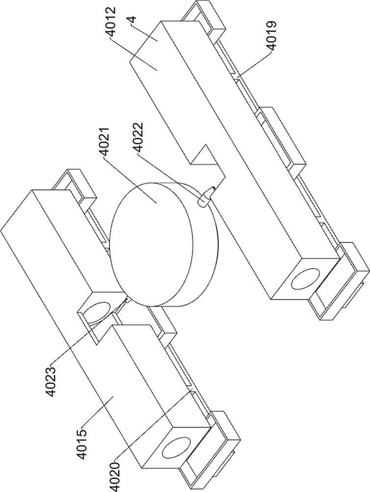
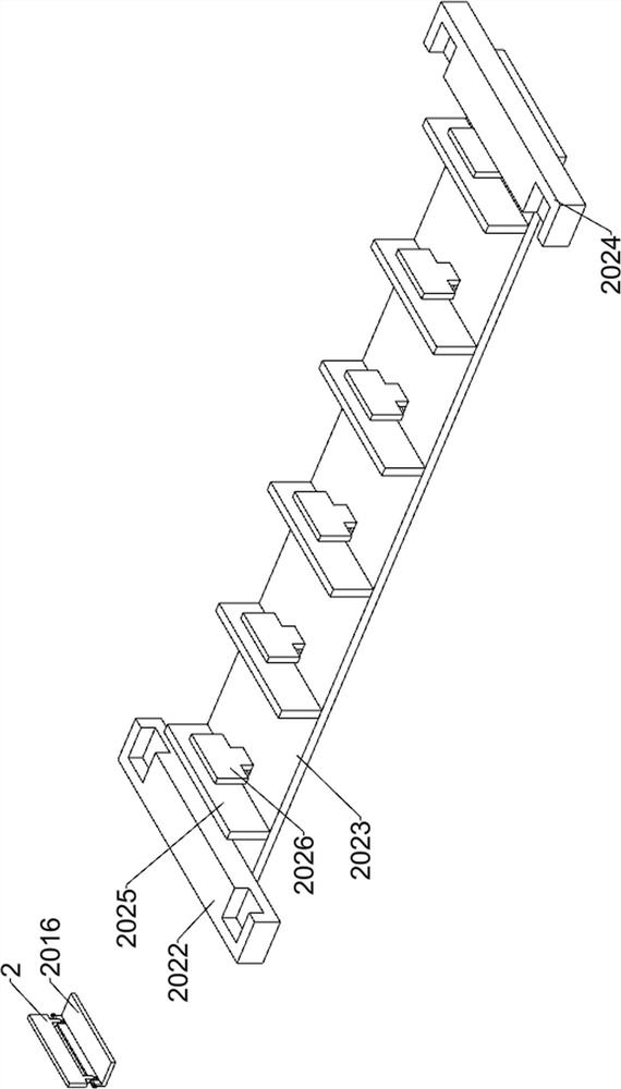
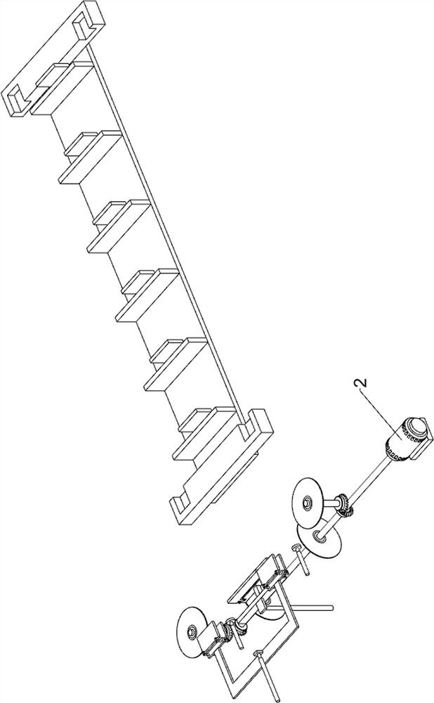
[0031] A ladder welding device based on a ground rail robot, such as Figure 1-11 As shown, it includes an underframe 1, a pendulum assembly 2, a transport assembly 3, a welding assembly 4, a base 5, a control panel 6, a first support block 7, a first anti-skid block 8, a first storage box 9 and a first limit The bit block 10; the bottom frame 1 is connected with the pendulum assembly 2; the bottom frame 1 is connected with the transport assembly 3; the bottom frame 1 is connected with the welding assembly 4; The screen 6 is fixedly connected; the base frame 1 is fixedly connected with the four sets of first support blocks 7; the base frame 1 is fixedly connected with the first storage box 9; the pendulum assembly 2 is connected with the welding assembly 4; 6 for fixed connection; four sets of first support blocks 7 are respectively fixedly connected with four groups of first anti-skid blocks 8;

[0032] Working principle: When preparing for work, place the device on a horizo...


PUM


Abstract

The invention relates to the field of ground rail robots, in particular to a crawling ladder welding device based on a ground rail robot. The technical problem to be solved is to provide the crawling ladder welding device based on the ground rail robot. According to the technical scheme, the crawling ladder welding device based on the ground rail robot comprises a material placing assembly, a welding assembly and the like, and the material placing assembly is connected with the welding assembly. When the crawling ladder welding device is used, cutting is carried out on an L-shaped cross rod in advance, the two ends of a horizontal part of the L-shaped cross rod exceed the two ends of a vertical part respectively, then the two ends of the horizontal part are lapped on two vertical rods respectively, the the welding operation is carried out, and therefore the problem of poor stability caused by a small welding area is eradicated, the L-shaped transverse rod is perpendicular to the two vertical rods at the same time and then the welding operation is carried out, the phenomenon that the transverse rods are inclined after welding is eradicated, welding is sequentially carried out on the six transverse rods through a ground rail, meanwhile, automatic lubrication can be achieved, and lubricating oil is prevented from dripping into the device.

Description

technical field [0001] The invention relates to the field of ground rail robots, in particular to a ladder welding device based on ground rail robots. Background technique [0002] With the continuous development of machine automation, the introduction of automation in various industries is in full swing, and the application of manipulators is becoming more and more extensive. However, due to the generally high price of manipulators, it would be a bit of a problem to put a manipulator on each station. Excess energy, plus some stations do not require a single manipulator to serve around the clock, so a device that can move the robot is derived - the ground rail. [0003] In the prior art, one of the ladders is composed of two cuboid vertical bars and several L-shaped horizontal bars. When the existing device produces this type of ladder, the two vertical bars are placed horizontally and parallel, and then multiple groups of L-shaped horizontal bars are placed. The rods are e...

Claims


Application Information

Patent Timeline
Patent Type & Authority Applications(China)
IPC IPC(8): B23K37/00B23P23/04F16N7/00F16N21/02F16N31/02
CPCB23K37/00B23P23/04F16N7/00F16N21/02F16N31/02
Inventor 孙瑞琴
Owner 孙瑞琴
Why Eureka
Try Eureka