Special blood station heat sealing machine with multi-connector function
What is Al technical title?
Al technical title is built by PatSnap Al team. It summarizes the technical point description of the patent document.
A multi-joint, heat-sealing machine technology, applied in the field of medical heat-sealing machines, can solve the problems of joint sealing failure, affecting clinical operations, time-consuming and labor-intensive problems, etc.
Active Publication Date: 2021-09-14
孙小敏
View PDF7 Cites 0 Cited by
Summary
Abstract
Description
Claims
Application Information
AI Technical Summary
This helps you quickly interpret patents by identifying the three key elements:
Problems solved by technology
Method used
Benefits of technology
Problems solved by technology
[0003]According to the above, at present, when blood matching and other operations are performed in blood stations, the clinical blood lines need to be thermally synthesized into blood lines of different lengths according to specific clinical needs , so the medical heat sealing machine of the prior art will be used, and in the specific operation heat sealing process, although the traditional medical heat sealing machine can meet the basic needs, there are corresponding defects; The location of the blood pressure line, and at the same time need to control the switch of the heat sealing machine, so it is very inconvenient and greatly affects the clinical operation; 2. Because there is only one heat sealing head on the traditional heat sealing machine, when multiple points or for blood bags are required to heat seal , it is necessary to carry out multiple times of heat sealing to complete the processing of several points, but this is not only time-consuming and laborious, resulting in too troublesome operation, but also affects the heat sealing effect, resulting in the failure of the butt joint seal. In view of the above defects, it is necessary to design a multi- Special heat sealing machine for blood bank with joint function
Method used
Image
Click on the blue label to locate the original text in one second.
Reading with bidirectional positioning of images and text.
Examples
Embodiment Construction
[0022] In the following text, numerous specific details are set forth in order to provide a thorough understanding of the concepts underlying the described embodiments, however, it will be apparent to those skilled in the art that the described embodiments can be used without these specific details. Some or all instances were practiced, and in other instances well-known process steps were not described in detail.
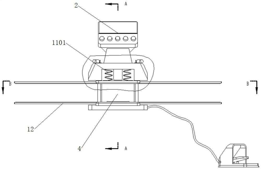
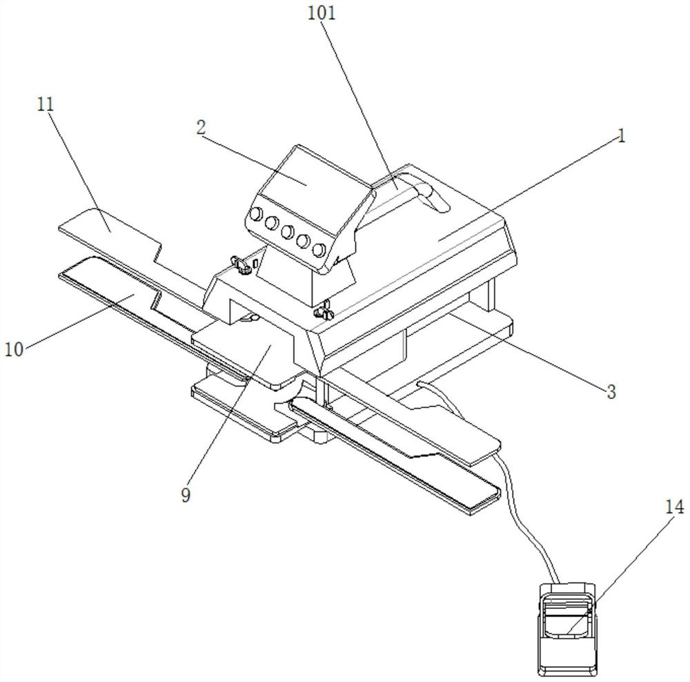
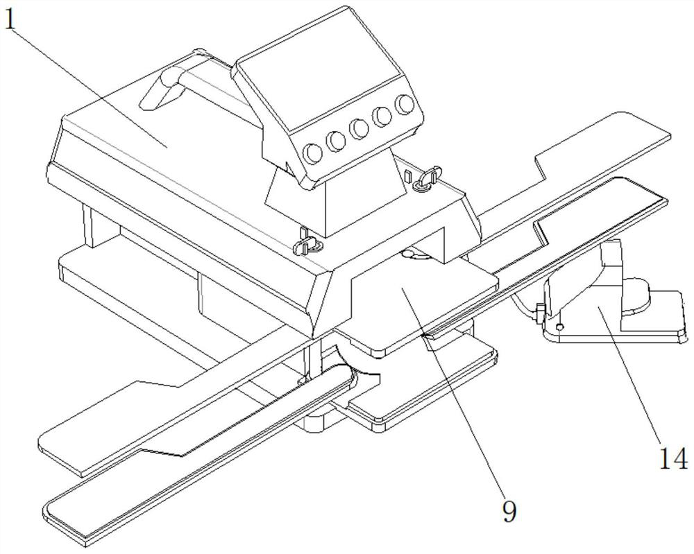
[0023] Such as figure 1 , figure 2 , image 3 , Figure 4 , Figure 5 , Image 6 , Figure 7 , Figure 8 , Figure 9 As shown, a special heat sealing machine for blood bank with multi-joint function, including workbench 1, temperature controller 2, avoidance groove 3, placement groove 4, electric push rod 5, heater 6, rotating shaft 7, I pressure plate 8 , II pressure plate 9, I heat conduction plate 10, I adjustment pressure plate 11, II adjustment pressure plate 12, II heat conduction plate 13, stepping switch 14, described thermostat 2 is fixedly arrange...
PUM
Abstract
The invention discloses a special blood station heat sealing machine with a multi-connector function. The special blood station heat sealing machine comprises a workbench, a temperature controller, avoiding grooves, an accommodating groove, an electric push rod, a heater, rotating shafts, a pressing plate I, a pressing plate II, a heat conducting plate I, an adjusting pressing plate I, an adjusting pressing plate II, a heat conducting plate II and a treading switch. The special blood station head sealing machine is ingenious in structure and convenient to operate. Firstly, the specific position of a heat sealing machine head can be adjusted according to the actual length of a pipeline to expand the heat sealing range and point positions, butt joint sealing of pipelines with different lengths or blood bags is met, meanwhile multilateral heat sealing can be directly achieved at a time, practicability is expanded, and working efficiency is improved; and secondly, through the pedal switch design, a medical worker can conveniently step on a switch, two hands are liberated, operation is optimized, other work on the hands is not affected, and finally the purpose of good clinical application and popularization is achieved.
Description
technical field [0001] The invention relates to the field of medical heat sealing machines, in particular to a special heat sealing machine for blood banks with multi-joint functions. Background technique [0002] The medical heat sealing machine, that is, the special medical welding machine is mainly used for heat sealing of blood catheters after blood collection; blood catheter heat sealing in the component blood preparation process includes aseptic heat sealing connections, and is also suitable for plastic blister boxes such as PVC and PET. Welding with composite paper for medical use, air-permeable paper, etc., as well as purification packaging for special medical industries, blood stations, Class I, Class II, and Class III medical devices, such as DuPont absorbent paper, PET, and medical PVC for welding and sealing medical plastic products It is also a special equipment for medical products. [0003] According to the above, when performing blood matching and other oper...
Claims
Application Information
Patent Timeline
Application Date:The date an application was filed.
Publication Date:The date a patent or application was officially published.
First Publication Date:The earliest publication date of a patent with the same application number.
Issue Date:Publication date of the patent grant document.
PCT Entry Date:The Entry date of PCT National Phase.
Estimated Expiry Date:The statutory expiry date of a patent right according to the Patent Law, and it is the longest term of protection that the patent right can achieve without the termination of the patent right due to other reasons(Term extension factor has been taken into account ).
Invalid Date:Actual expiry date is based on effective date or publication date of legal transaction data of invalid patent.