
System and method for stably recycling waste slurry in mixing plant

A mixing plant and stable technology, applied in the field of stable recycling of waste slurry in mixing plant, can solve the problems of pH value detection and requirements of waste slurry, accelerate the hydration of cement particles, shorten the setting time of cement and concrete, etc.

Pending Publication Date: 2021-09-14
中建西部建设西南有限公司 +1
View PDF12 Cites 0 Cited by
  • Summary
  • Abstract
  • Description
  • Claims
  • Application Information

AI Technical Summary

Problems solved by technology

[0004] The application number is 201610632968.5 Chinese invention patent discloses a waste recycling system and method for concrete mixing plants. The method detects and adjusts the solid content of the waste slurry, and controls the solid content of the waste slurry to 5-10%. The problems of this method include : (1) Since the waste slurry contains sandstone raw materials and sewage after ground washing, it carries some mud components, which is easy to produce significant adsorption of admixtures and increase the amount of concrete admixtures, but this method does not carry out this index Detection and requirements; (2) Under alkaline conditions, the hydration of cement particles will be accelerated, and the setting time of cement and concrete will be significantly shortened. In this method, there is no relevant detection and requirements for the pH value of waste slurry
(3) In this system, the slurry outlet pipe is located at the bottom of the waste slurry tank, and the waste slurry in the pipeline cannot flow back smoothly after pumping, and it is easy to cause insoluble matter to adhere to the pipeline and cause blockage if it is left in the pipeline
Therefore, although the solid content of waste slurry can be controlled according to this method, it will still cause fluctuations in the quality of concrete

Method used


Image

  • System and method for stably recycling waste slurry in mixing plant
  • System and method for stably recycling waste slurry in mixing plant

Examples


Embodiment Construction

[0033] In order to have a clearer understanding of the technical features, purposes and effects of the present invention, the specific implementation manners of the present invention will now be described in detail with reference to the accompanying drawings.

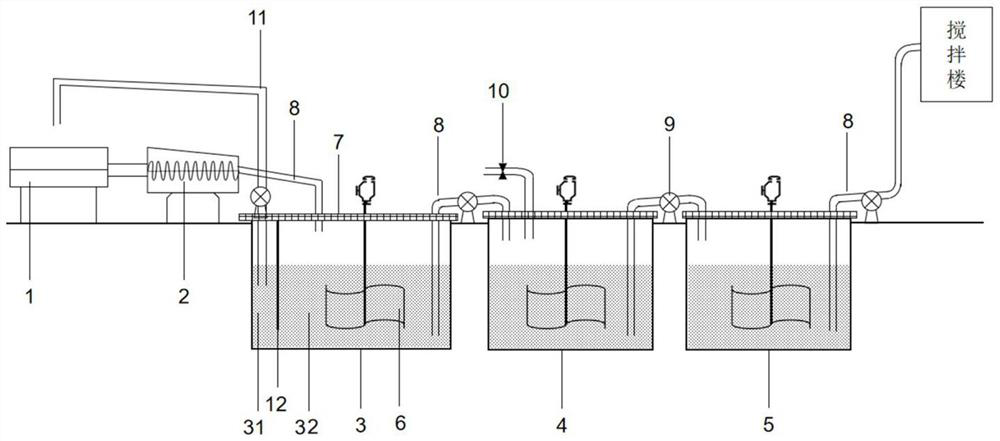
[0034] Such as figure 1 As shown, a system for the stable recycling of waste slurry in a mixing station provided by an embodiment of the present invention includes a tank car cleaning tank 1, a sand separator 2, a recovery tank 3, a detection tank 4, a storage tank 5 and a clean water supply System 10. The tank car cleaning tank 1 is connected with the sand and gravel separator 2, and the recovery tank 3, the detection tank 4 and the storage tank 5 are connected in sequence through the water guide pipe 8 and the water pump 9. The waste concrete and waste slurry water in the tank car cleaning tank 1 are separated into waste slurry and solid waste by the sand separator 2. The solid waste can be screened into sand and sto...


PUM


Abstract

The invention relates to a system and method for stably recycling waste slurry in a mixing plant. A tank car cleaning tank is connected with a sand-stone separator, and a recycling pool, a detection pool and a storage pool are sequentially connected through a water guide pipe and a water pump; a partition plate is arranged in the recycling pool and divides the recycling pool into a first recycling pool and a second recycling pool, the bottom of the first recycling pool and the bottom of the second recycling pool are communicated, a recycling cleaning pipe is arranged in the first recycling pool, the bottom of the recycling cleaning pipe is located on the upper middle portion of the recycling pool, the other end of the recycling cleaning pipe is connected to the position above the tank car cleaning tank, and a water guide pipe connected with the sand-stone separator is arranged in the second recycling pool; the detection pool is used for sampling detection and adjustment of waste slurry and is connected with a clear water supply system; and the storage pool is used for storing the qualified waste slurry, and is directly used for concrete production. Quality fluctuation of the waste slurry in the using process can be eliminated, stable utilization of the waste slurry for concrete production is achieved, and meanwhile, the recycling rate of the waste slurry can be effectively increased.

Description

technical field [0001] The invention relates to the technical field of waste pulp recycling, in particular to a system and method for stable recycling of waste pulp in a mixing station. Background technique [0002] Due to the increasing demand for concrete, the production of commercial concrete mixing plants is also increasing. In the process of concrete production, a large amount of waste slurry is used for washing, mixing, transportation, and cleaning of pumping equipment and sites. big waste. Relevant data show that an annual production capacity of 500,000 m 3 The wastewater discharged by the mixing plant is as high as 80,000 tons; an annual production capacity of 200,000 m 3 The concrete plant produces wastewater of up to 30m per day 3 ; The annual production capacity of concrete is about 1.2 million m 3 The waste water produced by the cleaning equipment of the mixing station reaches 60t every day. The treatment of wastewater from mixing plants is one of the most c...

Claims


Application Information

Patent Timeline
Patent Type & Authority Applications(China)
IPC IPC(8): C02F9/02
CPCC01F1/00C02F2001/007
Inventor 袁文韬张武宗王军张远兰聪刘东郑学奇刘霞祝云
Owner 中建西部建设西南有限公司
Learn More