Robot force control end effector and control method thereof

A technology of end effector and robot, which is applied in the direction of automatic grinding control device, workpiece feed movement control, manufacturing tools, etc. It can solve the problems of poor control performance, large mechanical vibration, slow response speed, etc., and achieve simple and compact structure , reduce noise and vibration, slow response effect

Active Publication Date: 2021-09-17
TIANJIN UNIVERSITY OF TECHNOLOGY
View PDF9 Cites 3 Cited by
  • Summary
  • Abstract
  • Description
  • Claims
  • Application Information

AI Technical Summary

Problems solved by technology

However, the pneumatic drive method has disadvantages such as slow response speed and hysteresis, and the mechanical structure transmission has defects such as complex mechanism, large mechanical vibration during motion, and poor control performance.

Method used


Image

  • Robot force control end effector and control method thereof
  • Robot force control end effector and control method thereof
  • Robot force control end effector and control method thereof

Examples


Embodiment 1

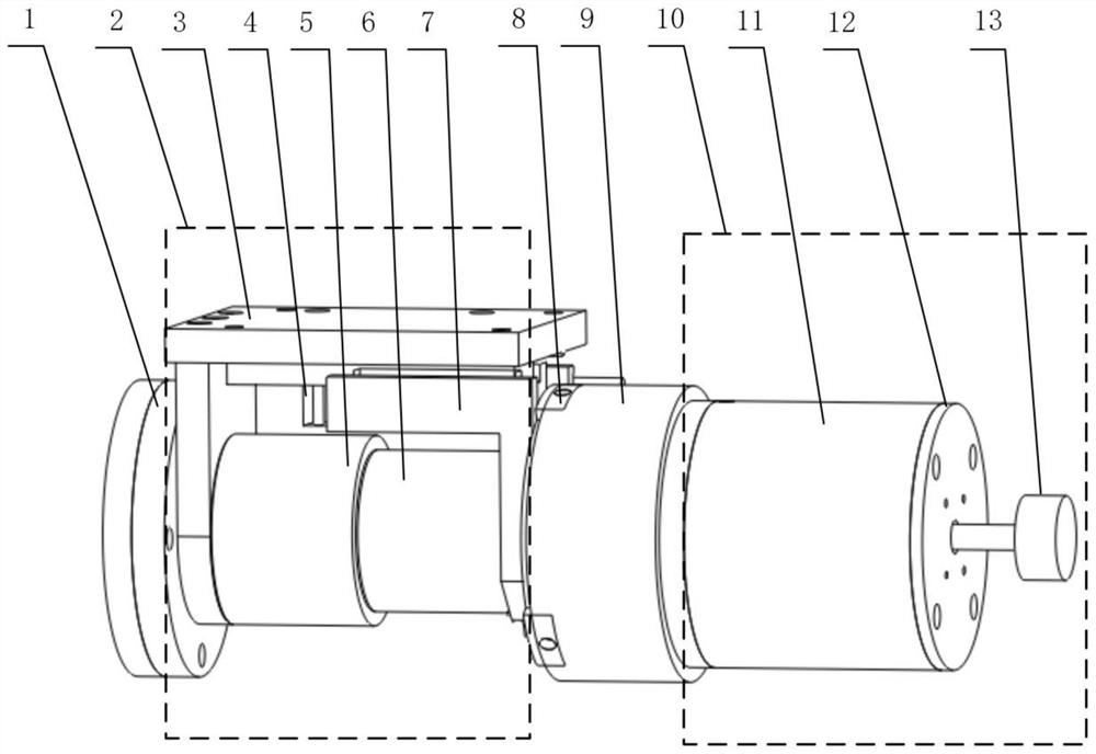
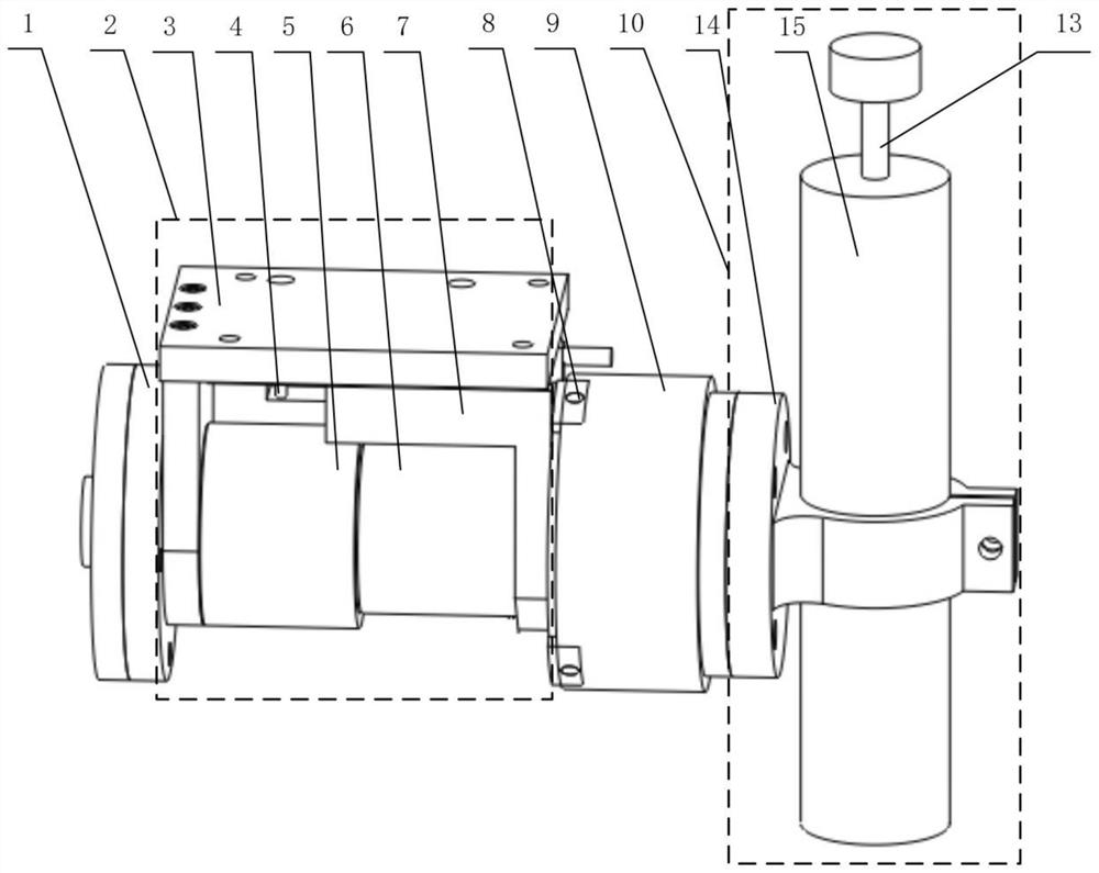
[0038] A force-controlled end effector for a robot, comprising: a connecting flange 1, a voice coil motor module 2, a force sensor 9, a controller, and a grinding module 10, and the voice coil motor module 2 includes: a voice coil motor, a bracket 3, and a linear guide rail 7 and the displacement sensor 4, the linear guide 7 and the stator of the voice coil motor are fixed on the bracket 3, the mover of the voice coil motor is fixed to the slider on the linear guide, and the linear guide is used as a guide connecting the mover and stator of the voice coil motor The device is used to connect the flange 1 and the bracket 3, and is used to fix the voice coil motor module 2 and the robot, so as to realize the connection between the pose control of the robot and the grinding and polishing force control of the force-controlled end effector of the robot; the force sensor One end of 9 is fixedly installed with the mover of the voice coil motor, and the other end is installed with a gri...

Embodiment 2

[0041] On the basis of Embodiment 1, the force sensor 9 is fixed to the mover of the voice coil motor through a mounting flange 8 . The electric spindle is parallel to the sliding direction of the slide block on the linear guide rail 7 (axial grinding) or vertical (radial grinding).

Embodiment 3

[0043] On the basis of Embodiment 2, when the electric spindle is parallel to the sliding direction of the slider on the linear guide rail 7, the grinding module 10 further includes: a sleeve 11, the sleeve 11 is installed on the force sensor 9, and one end of the electric spindle is positioned on the sleeve The other end of the cylinder 11 protrudes from the sleeve 11 and is fixed with the grinding head 13 . The electric spindle is fixedly installed with the sleeve through the fixing flange 12.


PUM


Abstract

The invention discloses a robot force control end effector and a control method thereof. The robot force control end effector comprises a connecting flange, a voice coil motor module and a grinding module. The voice coil motor module comprises a voice coil motor, a support, a linear guide rail and a displacement sensor, the linear guide rail and a stator of the voice coil motor are both fixedly mounted on the support, a rotor of the voice coil motor and a sliding block on the linear guide rail are fixedly mounted, and the connecting flange and the support are fixedly mounted. One end of a force sensor and the rotor of the voice coil motor are fixedly mounted, the grinding module is mounted at the other end of the force sensor, the displacement sensor is mounted on the linear guide rail, and the grinding module comprises an electric spindle and a grinding head fixedly mounted at one end of the electric spindle. The controller reads signals of the force sensor and the displacement sensor and controls the voice coil motor and the electric spindle. The controller is adopted for processing the signals of the displacement sensor and the signals of the force sensor, and constant-force grinding control over the end effector is achieved through real-time adjustment of the grinding and polishing force and the posture of the robot force control end effector.

Description

technical field [0001] The invention belongs to the technical field of automation equipment and robots, and in particular relates to a robot force-controlled end effector and a control method thereof. Background technique [0002] With the increasing demands on the surface quality of free-form workpieces, such as large fan blades, aircraft turbine blades and propellers, the polishing process is complicated and accompanied by higher and higher precision levels required. At present, most polishing still requires skilled technicians to do it manually, which has the problems of high risk, high labor intensity, high processing cost, low operating efficiency and low precision. In order to solve the limitations and deficiencies of manual polishing, robotic polishing systems and other types of automatic polishing equipment have been proposed and developed. Among them, industrial robots have the advantages of low price, large working space, and strong flexibility, but they lack forc...

Claims


Application Information

Patent Timeline
Patent Type & Authority Applications(China)
IPC IPC(8): B24B19/00B24B41/00B24B41/04B24B47/20B24B49/12B24B51/00
CPCB24B19/00B24B41/04B24B47/20B24B51/00B24B41/00B24B49/12
Inventor 周海波马世泰王桂莲赵磊王勇邓誉鑫周顺
Owner TIANJIN UNIVERSITY OF TECHNOLOGY
Why Eureka
Try Eureka