
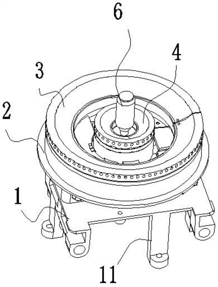
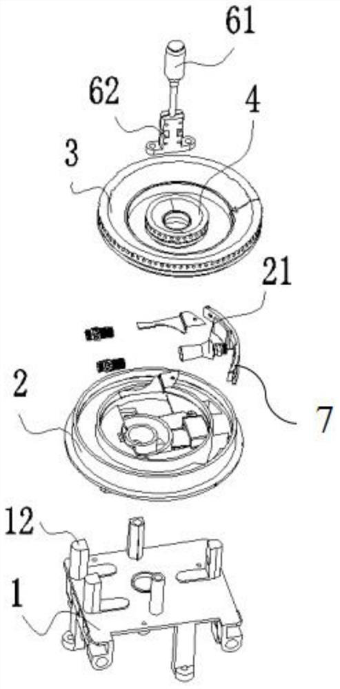
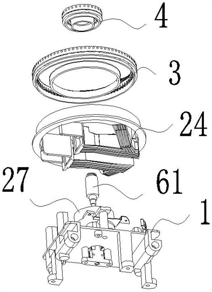
Upper air inlet burner

A burner and fire distributor technology, which is applied to burners, gas fuel burners, combustion methods, etc., can solve the problems of short gas-air mixing time, insufficient mixing uniformity, uneven distribution of gas, etc., and achieve reasonable structural space layout. , Improve the ejection performance, the effect of superior practicability

Pending Publication Date: 2021-09-17
李彩红
View PDF0 Cites 0 Cited by
  • Summary
  • Abstract
  • Description
  • Claims
  • Application Information

AI Technical Summary

Problems solved by technology

[0002] According to market research and patent retrieval, the existing burner uses the center as the gas outlet, the gas is not uniformly dispersed, the gas-air mixing time is short, and the mixing uniformity is not enough to make the combustion insufficient; and the temperature of the injector tube is high, so that The hot air resistance is relatively large, the air supply is not smooth, the safety is reduced, and the production cost is high and other factors are affected
The central injection tube is injected vertically upwards. Due to structural limitations, the injection tube is short and the mixture of gas and air is not sufficient, which may easily cause incomplete combustion; the outer ring injection tube is easy to receive heat, resulting in a higher temperature of the mixture of air and gas in the injection tube. , it is easy to cause tempering, and it is impossible to install an anti-dry probe

Method used


Image

  • Upper air inlet burner
  • Upper air inlet burner
  • Upper air inlet burner

Examples


Embodiment Construction

[0021] Embodiments of the present invention are described in detail below, examples of which are shown in the drawings, wherein the same or similar reference numerals represent the same or similar elements or elements having the same or similar functions throughout.

[0022] The orientations shown in the drawings should not be construed as limiting the specific protection scope of the present invention, but are only for reference and understanding of preferred embodiments, and the product components shown in the drawings can be changed in position or increased in number or simplified in structure.

[0023] The "connection" described in the specification and the "connection" relationship between the parts shown in the drawings can be understood as fixed connection or detachable connection or integral connection; it can be directly connected or connected through an intermediary. Those of ordinary skill in the art can understand the connection relationship according to the specifi...


PUM


Abstract

An upper air inlet combustor comprises a furnace end, a furnace body, an outer ring fire cover and a center fire cover. The furnace body is provided with an injection pipe and a combustion gas supply channel. A gas outlet of the combustion gas supply channel deviates from the center of the furnace body. A horn mouth injection cylinder is arranged in the injection pipe and is provided with an injection cavity which is gradually enlarged outwards, and the injection cavity is aligned to a gas nozzle. A gas outlet is located in a center fire cover cavity, the center fire cover covers the center fire cover cavity so that the gas outlet can communicate with the center fire cover cavity, and gas enters the center fire cover cavity from the gas outlet and is blocked by the center fire cover to be evenly dispersed into the center fire cover cavity. An outer fire distributor and an inner fire distributor are of a detachable split structure. According to the upper air inlet burner, the injection pipe is horizontally arranged, the length of the injection pipe is increased, the injection performance is improved, heat dissipation strips are additionally arranged on outer ring injection pipes, a center injection air outlet is arranged in an offset mode, combustion is more sufficient, flames are stable, the heat efficiency of combustion is effectively improved, and the structural space arrangement is reasonable.

Description

technical field [0001] The invention relates to an upward air intake burner. Background technique [0002] According to market research and patent retrieval, the existing furnace head uses the center as the gas outlet, the gas is not uniformly dispersed, the gas-air mixing time is short, and the mixing uniformity is not enough to make the combustion insufficient; and the temperature of the injector tube is high, so that The hot air resistance is relatively large, the air supply is not smooth, the safety is reduced, and various factors such as high manufacturing cost are affected. The central injection tube is injected vertically upwards. Due to the structural limitation, the injection tube is short and the mixture of gas and air is not sufficient, which may easily cause incomplete combustion; the outer ring injection tube is easy to receive heat, resulting in a higher temperature of the mixture of air and gas in the injection tube. , It is easy to cause tempering, and it is...

Claims


Application Information

Patent Timeline
Patent Type & Authority Applications(China)
IPC IPC(8): F23D14/02F23D14/46F23D14/58F23D14/62F23D14/72
CPCF23D14/02F23D14/46F23D14/58F23D14/62F23D14/72
Inventor 李彩红
Owner 李彩红
Learn More