
Spectrometer

A spectrometer, spectroscopic technology, applied to a spectrometer. In the field, it can solve volume conflicts, affect spectral quality, and lengthen optical path, and achieve the effects of improving optical efficiency and spectral quality, improving spectral quality, and reducing volume

Pending Publication Date: 2021-09-17
INNOSPECTRA CORP
View PDF0 Cites 2 Cited by
  • Summary
  • Abstract
  • Description
  • Claims
  • Application Information

AI Technical Summary

Problems solved by technology

[0003] However, the light collection efficiency of the known sampling module is poor after diffuse reflection, usually by increasing the wattage of the bulb or increasing the number of bulbs to enhance the intensity of the light source to increase the light collection efficiency, but increasing the light source intensity or increasing the number of bulbs will Increase the load on the system power supply and increase power consumption, while increasing heat energy, resulting in measurement errors
[0004] Another sampling module uses a bulb with a reflector cup to increase the light intensity irradiated on the object to be measured, but the volume of the bulb containing the reflector cup is too large, which will cause volume conflicts for the design of the reflective module, which is not conducive to Applications of Handheld Spectrometers
In addition, the configuration of the bulbs is also difficult to concentrate. The distance between each bulb increases, and the distance from the bulb to the object to be measured also increases. Although the reflector cup can increase the light output efficiency, as the distance from the bulb to the object to be measured increases, The longer the optical path, the lower the light collection efficiency, and more serious stray light will affect the spectral quality

Method used


Image

  • Spectrometer
  • Spectrometer
  • Spectrometer

Examples


Embodiment Construction

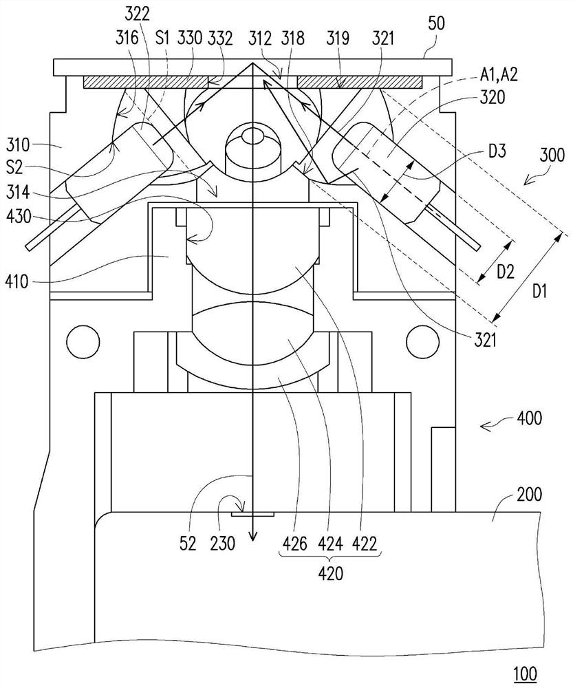
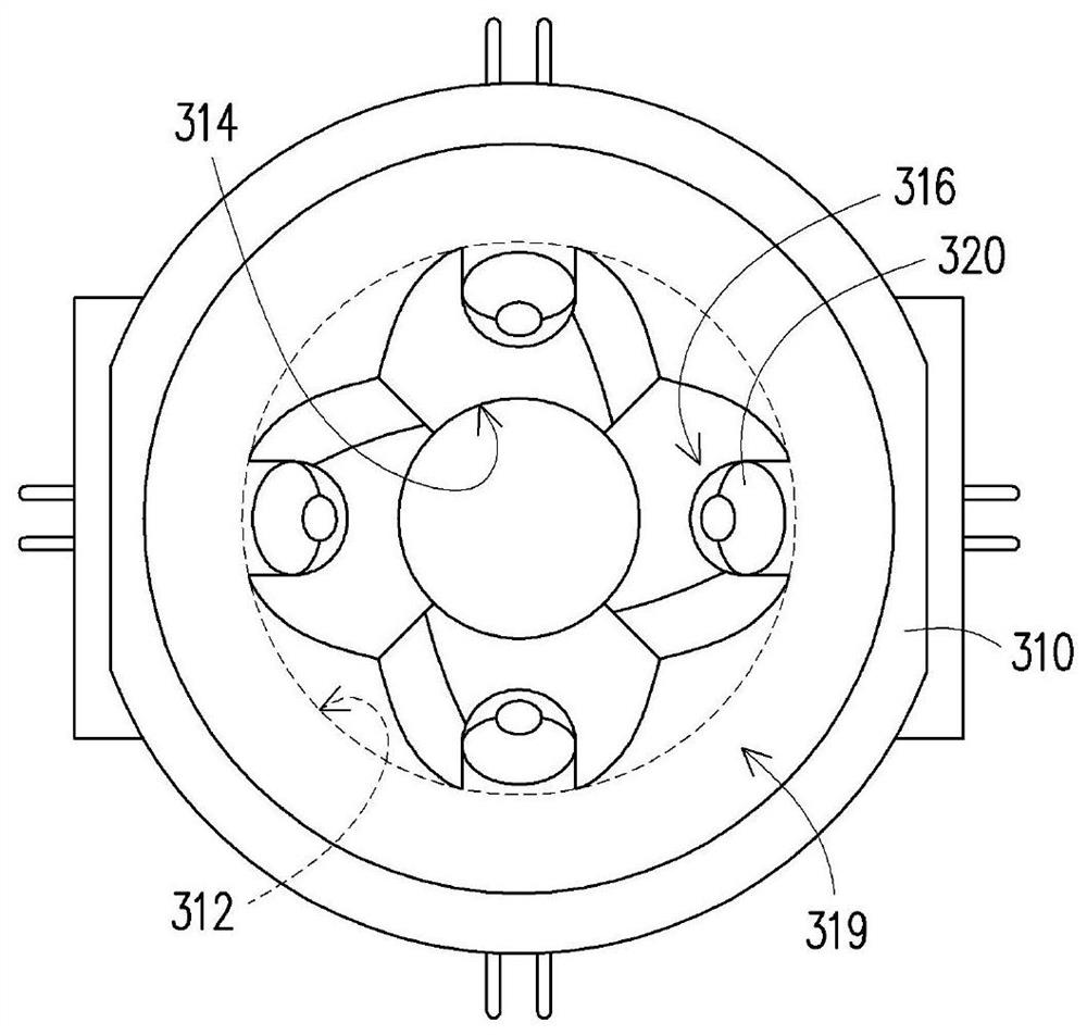
[0044] figure 1 is a schematic cross-sectional view of a spectrometer according to an embodiment of the present invention, and figure 2 for figure 1 Front view of the part sampling module of the spectrometer. Please refer to figure 1 and figure 2 , the spectrometer 100 of this embodiment is used to measure the spectrum of the object 50 to be tested, and the spectrometer 100 includes a spectrometer main body 200 and a sampling module 300 . The spectrometer main body 200 has a light entrance 230 , and the sampling module 300 is disposed on the spectrometer main body 200 to form the spectrometer 100 . The sampling module 300 includes a light source fixing base 310 and at least one light source 320 (a plurality of light sources 320 are taken as an example in this embodiment). The light source fixing seat 310 has a first opening 312 and a second opening 314 opposite to each other and at least a cup-shaped reflective surface 316 (in this embodiment, a plurality of cup-shaped ...


PUM

PropertyMeasurementUnit
diameteraaaaaaaaaa
absorbanceaaaaaaaaaa

Abstract

A spectrograph is used for measuring the spectrum of an object to be measured, and comprises a spectrograph main body and a sampling module, wherein the spectrograph main body is provided with a light inlet, and the sampling module is configured on the spectrograph main body. The sampling module comprises a light source fixing seat and at least one light source. The light source fixing base is provided with at least one cup-shaped reflection curved surface. The light source is arranged on the light source fixing seat, and the cup-shaped reflection curved surface surrounds the light source. Herein, illuminating light emitted by the light source is reflected and converged by the cup-shaped reflecting curved surface to be transmitted to the to-be-measured object, the to-be-measured object diffusely reflects the illuminating light into to-be-measured light, and the to-be-measured light enters the spectrograph main body through the light inlet and is measured by the spectrograph main body. According to the invention, high spectral quality can be achieved, and the device can have a small size.

Description

【Technical field】 [0001] The present invention relates to an optical device, and in particular to a spectrometer. 【Background technique】 [0002] Generally speaking, the sampling module of a spectrometer includes at least one light bulb and a light-receiving lens. The light bulb projects the light to the sample on the waiting side. After the light enters the sample on the waiting side, it passes through the light-receiving lens through diffuse reflection, and finally enters the spectrometer to obtain the spectral information of the sample. . [0003] However, the light collection efficiency of the known sampling module is poor after diffuse reflection, usually by increasing the wattage of the bulb or increasing the number of bulbs to enhance the intensity of the light source to increase the light collection efficiency, but increasing the light source intensity or increasing the number of bulbs will Increase the load on the system power supply and increase power consumption,...

Claims


Application Information

Patent Timeline
Patent Type & Authority Applications(China)
IPC IPC(8): G01J3/28G01J3/02G01J3/10G01N21/25G01N21/01
CPCG01J3/28G01J3/0216G01J3/0208G01J3/0291G01J3/10G01N21/25G01N21/255G01N21/01G01N2021/0112G01J3/42G01J2003/102G01J2003/425G01J3/0262G01J3/0235G01J3/0256G01J3/0272
Inventor 张飞鹏黄国胜李锡滨
Owner INNOSPECTRA CORP
Learn More