Traveling wave fault positioning method based on directed tree model and linear fitting

A linear fitting, traveling wave fault technology, applied in fault location, fault detection according to conductor type, measurement device, etc., can solve the problem of inability to comprehensively utilize the fault location information of the transmission network, and achieve the elimination of fault traveling wave non-shortest path, Avoid weighted imbalance and easy fault location

Inactive Publication Date: 2021-09-17
CHANGSHA UNIVERSITY OF SCIENCE AND TECHNOLOGY
View PDF0 Cites 1 Cited by
  • Summary
  • Abstract
  • Description
  • Claims
  • Application Information

AI Technical Summary

Problems solved by technology

[0006] The invention provides a traveling wave fault location method based on a directed tree model and linear fitting. The proposed method solves the problem of fault location caused by abnormal conditions such as failure of a positioning device in the transmission network, startup failure, or time record error. The problem of failure solves the problem that some existing positioning methods cannot comprehensively utilize the fault location information of the entire transmission network, and at the same time eliminates the influence of the uncertainty of traveling wave velocity and the error of fault traveling wave time recording on the positioning accuracy, and can realize The automatic de-looping of the transmission network ring network improves the reliability and accuracy of fault location

Method used


Image

  • Traveling wave fault positioning method based on directed tree model and linear fitting
  • Traveling wave fault positioning method based on directed tree model and linear fitting
  • Traveling wave fault positioning method based on directed tree model and linear fitting

Examples


Embodiment Construction

[0030] In order to make the technical solutions implemented by the present invention and the functions realized clearer, the present invention will be further described below in conjunction with the accompanying drawings and embodiments.

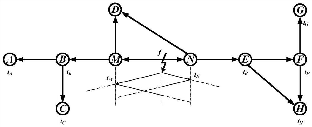
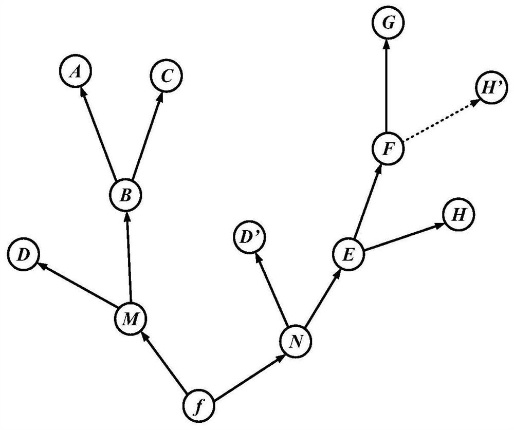
[0031] The fault initial traveling wave is transmitted along the shortest path in the entire power grid to form a fault initial traveling wave transmission network, such as figure 1 shown. The invention adopts graph theory method to analyze the network and proposes a directed tree model constructed by the shortest path directed tree. A directed tree model such as figure 2 As shown, the fault point f is defined as the root node of the tree. M and N are the root nodes of the subtree. Finding the shortest path for the traveling wave to travel from the fault point f is equivalent to finding the shortest path for M and N to transmit to the left and right ends respectively. The shortest path from the root node of the subtree to each substation ...


PUM


Abstract

The invention discloses a traveling wave fault positioning method based on a directed tree model and linear fitting. The method comprises the following steps of: 1) judging a fault line of a power transmission network; 2) defining the fault power transmission network as a directed tree model; 3) calculating the shortest path from each end point in the power transmission network to the end point of the fault line; 4) fitting two fitting straight lines according to a linear fitting principle; (5) judging whether each end point meets the condition that the absolute value of the difference of tk' and tk is less than or equal to 1 microsecond, if so, executing the step (6), otherwise, returning to the step (4); (6) judging whether the slopes of the two fitting straight lines meet the requirements or not, if so, executing the step (7), otherwise, returning to the step (4); and 7) finally obtaining the longitudinal coordinate of the intersection point of the two fitting straight lines, namely the fault distance, and ending the positioning process. The fault positioning of the power transmission network is realized by utilizing the directed tree model and the linear fitting principle, the whole network information is comprehensively utilized, the interference of wave velocity and time recording error on the fault positioning can be eliminated, the fault distance can be directly obtained from the coordinate plane, the principle is simple, and the positioning error is small.

Description

technical field [0001] The invention relates to the technical field of transmission network traveling wave location; in particular, it relates to a traveling wave fault location method based on a directed tree model and linear fitting when a fault location device in the transmission network fails. Background technique [0002] With the rapid development of the smart grid, the capacity of the power system and the area of ​​the power grid continue to expand, making the operation and management of the power grid more and more complex. If the location of the fault can be quickly and accurately determined after a fault occurs on the transmission line, it will not only reduce the burden on the staff to inspect and repair the line, but also reduce the loss caused by the power outage to the overall economy. Therefore, high-precision grid fault location is of great significance to the safe, stable and economical operation of the power system. [0003] The location of fault points on...

Claims


Application Information

Patent Timeline
Patent Type & Authority Applications(China)
IPC IPC(8): G01R31/08
CPCG01R31/085G01R31/088Y04S10/52
Inventor 曾举鹏喻锟喻泉曾祥君刘丰叶勇
Owner CHANGSHA UNIVERSITY OF SCIENCE AND TECHNOLOGY
Why Eureka
Try Eureka