Method and system for producing high-controllability off-axis optical bottle

An optical and off-axis technology, applied in the field of optics, can solve the problems of less adjustable parameters, difficult application, and small off-axis degree of light bottles, and achieve the effect of strong controllability, high off-axis degree and high degree of freedom

Active Publication Date: 2021-09-17
SOUTH CHINA NORMAL UNIVERSITY
View PDF7 Cites 1 Cited by
  • Summary
  • Abstract
  • Description
  • Claims
  • Application Information

AI Technical Summary

Problems solved by technology

However, judging from the current technology, most of the types of light bottles produced are single along-axis light bottles, that is, the light bottles are generated on th

Method used


Image

  • Method and system for producing high-controllability off-axis optical bottle
  • Method and system for producing high-controllability off-axis optical bottle
  • Method and system for producing high-controllability off-axis optical bottle

Examples


Embodiment 1

[0082] Embodiment one and Image 6 In this condition, the circular Pierce-Gaussian beam modulated by the compound second-order chirped vortex phase can be stably generated in free space. Narrower, longer off-axis optical vials.

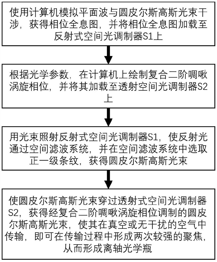
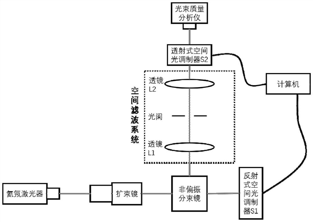
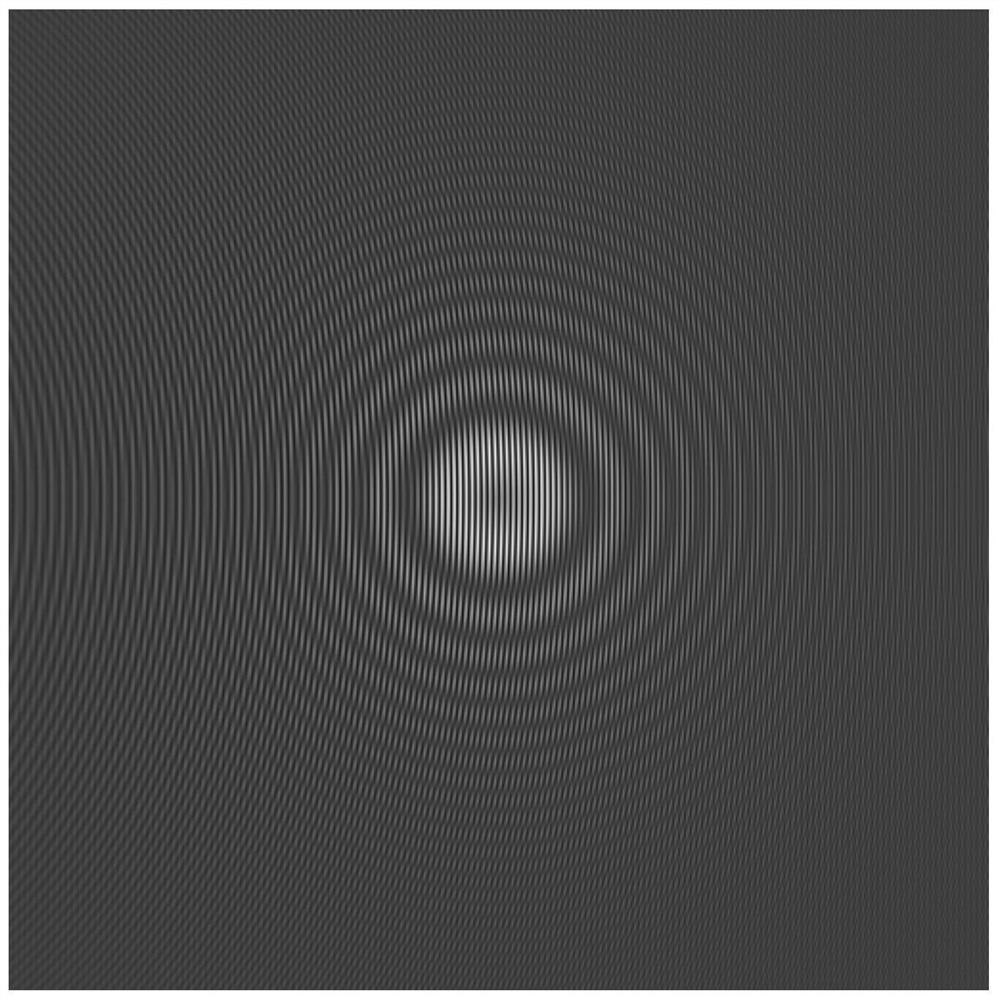
[0083] S01. Using a computer to simulate interference between a plane wave and a circular Pierce-Gaussian beam to obtain a phase hologram, and load the phase hologram onto the reflective spatial light modulator S1.

[0084] S02, according to the optical parameters, draw the composite second-order chirped vortex phase (N=2, l on the computer) 1 = 3, l2 = 3,c 1 =0.35, c 2 =0.25, (x 1 ,y 1 )=(0.0011, 0)), and it is loaded on the transmissive spatial light modulator S2, the composite second-order chirped vortex phase is as follows Figure 8 (a) shown.

[0085] S03. Irradiate the reflective spatial light modulator S1 with a light beam, make the reflected light pass through the spatial filtering system, and select positive first-order fringes in the ...

Embodiment 2

[0090] Embodiment two and Figure 7 In this condition, the circular Pierce-Gaussian beam modulated by the compound second-order chirped vortex phase can stably generate a beam that is closer to the initial plane and farther from the optical axis in free space, and the bottom of the bottle is narrow and the mouth of the bottle is narrow. Wider, longer off-axis optical vials.

[0091] S01. Using a computer to simulate interference between a plane wave and a circular Pierce-Gaussian beam to obtain a phase hologram, and load the phase hologram onto the reflective spatial light modulator S1.

[0092] S02, according to the optical parameters, draw the composite second-order chirped vortex phase (N=3, l on the computer) 1 = 2, l 2 = 2, l 3 = 2,c 1 =0.35, c 2 =0.25, c 3 =0.18, (x 1 ,y 1 )=(0.0005, 0)), and it is loaded on the transmissive spatial light modulator S2, the composite second-order chirped vortex phase is as follows Figure 8 (b) shown.

[0093] S03. Irradiate the...


PUM


Abstract

The invention provides a method and system for producing a high-controllability off-axis optical bottle, and the method comprises the steps: simulating the interference between a plane wave and a round Pearl Gaussian beam through a computer, obtaining a phase hologram, and loading the phase hologram to a reflective spatial light modulator; drawing a composite second-order chirp vortex phase on a computer according to the optical parameters, and loading the composite second-order chirp vortex phase to a transmission-type spatial light modulator; irradiating a reflective spatial light modulator by using a Gaussian beam, enabling reflected light to pass through a spatial filtering system, and selecting positive first-order stripes to obtain a round Pearl Gaussian beam; a circular Pearl Gaussian beam passes through a transmission-type spatial light modulator to obtain a circular Pearl Gaussian beam subjected to composite second-order chirp vortex phase modulation, and the circular Pearl Gaussian beam is transmitted in vacuum or interference-free air, so that strong focusing can be formed for multiple times in the transmission process, and an off-axis optical bottle is formed. The method and system can continuously regulate and control the off-axis optical bottle, is more efficient in the aspects of particle capture and control, and is high in degree of freedom.

Description

technical field [0001] The invention relates to the field of optical technology, in particular to a method and system for producing highly controllable off-axis optical bottles. Background technique [0002] The so-called "light bottle" refers to a closed dark space structure formed during the propagation of three-dimensional light beams. This concept was proposed by J.Arlt et al. in 2000. Compared with the optical tweezers proposed by A.Ashkin et al. in 1986, which can only manipulate a single particle, the optical vial, due to its unique structure, can Realize the manipulation of multi-particles, which has attracted much attention. [0003] Furthermore, in 2018, X.Y.Chen et al. proposed circular Pierce beams. As a derived beam from the Pierce beam, it inherits the self-healing properties of the Pierce beam, and also has a strong focusing ability. More importantly, compared to circular Airy beams, circular Pierce beams do not oscillate after focusing. These properties m...

Claims


Application Information

Patent Timeline
IPC IPC(8): G02B27/00G02B27/09G21K1/00
CPCG02B27/0012G02B27/0927G21K1/006
Inventor 邓冬梅莫振武江骏杰许丹琳黄海琪
Owner SOUTH CHINA NORMAL UNIVERSITY
Why Eureka
Try Eureka