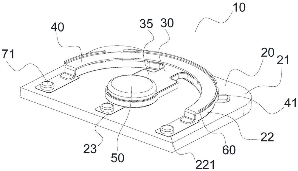
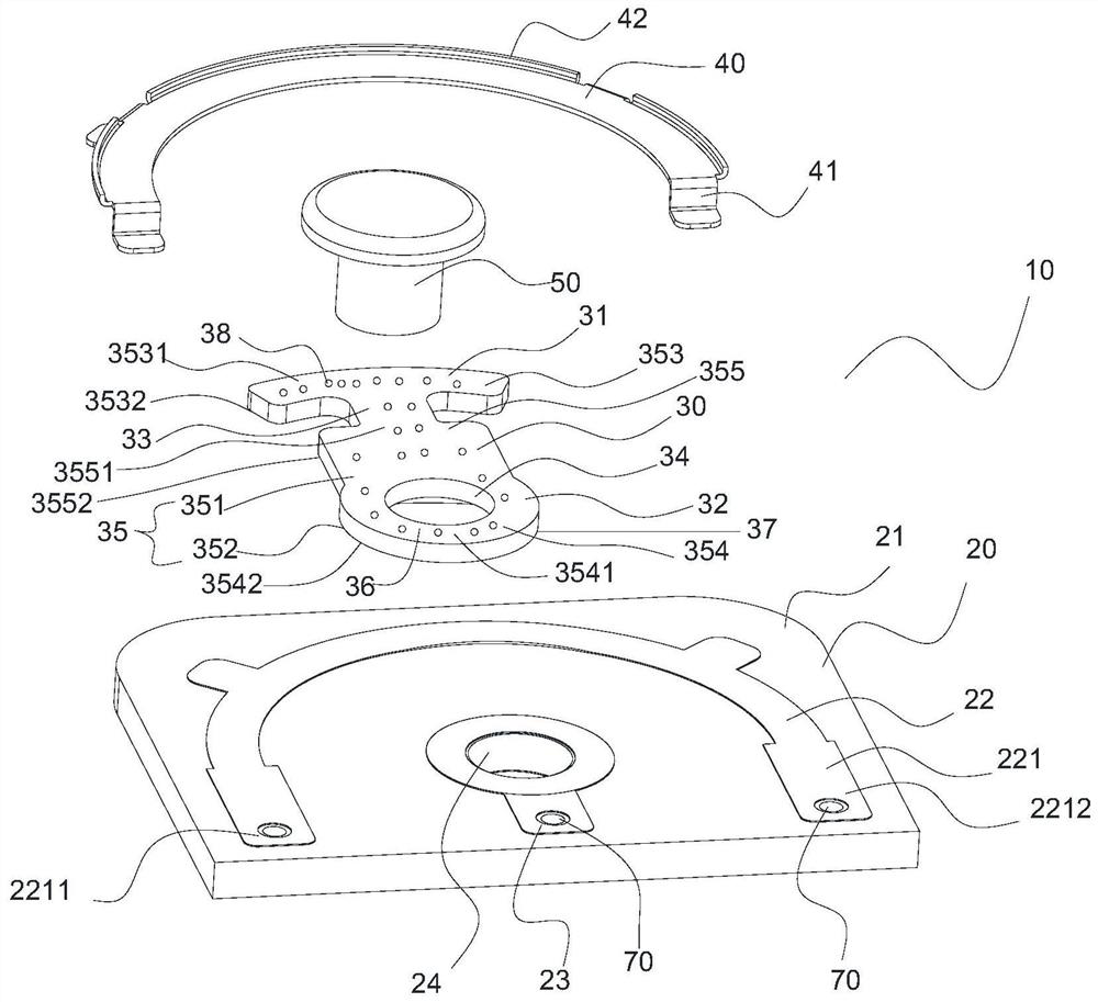
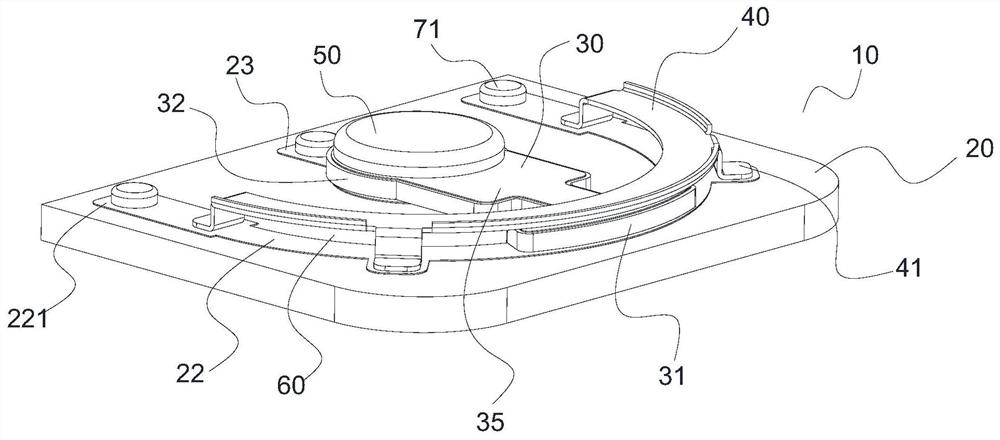
Base station, antenna and phase shifting device

A technology of phase shifting and transmission lines, which is applied in the field of base stations equipped with the antenna, which can solve the problems of increased push-pull force of the transmission structure, creep and looseness of the elastic crimping structure, and fluctuations in electrical indicators, so as to reduce the difficulty of assembly and production , Reduce wear and push-pull resistance, improve stability

Active Publication Date: 2022-05-24
COMBA TELECOM TECH (GUANGZHOU) CO LTD +1
View PDF11 Cites 0 Cited by
  • Summary
  • Abstract
  • Description
  • Claims
  • Application Information

AI Technical Summary

Problems solved by technology

[0003] At present, the industry provides a sector-shaped sliding phase shifter to solve the above problems. This sector-shaped sliding phase shifter has the advantages of simple circuit, small structure size and high phase shifting efficiency, but the gap between the sliding guide arm and the fixed circuit is It is electrically connected by being close to the coupling, and the change of the coupling gap will bring obvious fluctuations in the electrical index, and even affect the normal operation of the electric adjustable antenna
At present, the method commonly used in the industry is to stabilize the coupling connection structure by means of tight crimping, but this method has the following hidden dangers: 1. In the actual working environment, the elastic crimping structure will lose its elasticity with time and temperature changes It will gradually creep and loosen until it fails; 2. The tight structure directly causes the push-pull force of the transmission structure to increase, especially in the 5G Massive MIMO electronically adjustable antenna. The conventional 32TR electronically adjustable antenna needs to use 32 sets of phase shifters at the same time, and the combined total push-pull The force will bring a huge burden to the transmission structure, which will affect the service life of the compact structure

Method used


Image

  • Base station, antenna and phase shifting device
  • Base station, antenna and phase shifting device
  • Base station, antenna and phase shifting device

Examples


Embodiment Construction

[0037] The following describes in detail the embodiments of the present invention, examples of which are illustrated in the accompanying drawings, wherein the same or similar reference numerals refer to the same or similar elements or elements having the same or similar functions throughout. The embodiments described below with reference to the accompanying drawings are exemplary, and are only used to explain the present invention and should not be construed to limit the present invention.

[0038] It will be understood by those skilled in the art that the singular forms "a", "an", "the" and "the" as used herein can include the plural forms as well, unless expressly stated otherwise. It should be further understood that the word "comprising" used in the description of the present invention refers to the presence of stated features, integers, steps, operations, elements and / or components, but does not exclude the presence or addition of one or more other features, Integers, ste...


PUM


Abstract

The invention provides a base station, an antenna, and a phase shifting device, wherein the phase shifting device includes a fixed dielectric plate, a movable dielectric plate, and a limiting member; the pivoting end of the movable dielectric plate can be pivotally mounted on the fixed dielectric plate, A fixed transmission line is arranged on the fixed medium plate, and the fixed transmission line is extended along the rotation path of the free end of the movable medium plate, and the two ends of the fixed transmission line respectively form signal output ports; at least one surface of the movable medium plate is provided with a movable transmission line, the movable The transmission line is electrically connected to the signal input port on the fixed medium plate; the limiter is arranged parallel to the fixed medium plate along the extension path of the fixed transmission line, so as to jointly define with the fixed transmission line for the free end of the movable medium plate to perform rotational movement Arc-shaped slits for phase shifting. The phase shifting device of the present invention has a compact overall structure, is easy to install, occupies a small space, and has good phase shifting performance, and is especially suitable for 5G Mass i ve MI MO electric tuning antennas.

Description

technical field [0001] The present invention belongs to the technical field of mobile communication, and particularly relates to a phase shifting device, an antenna equipped with the phase shifting device, and a base station equipped with the antenna. Background technique [0002] In mobile communication, the electronically modulated antenna usually needs to use a phase shifter to change the phase difference of each array element, thereby controlling the spatial direction of the beam. Especially in the 5G Massive MIMO ESC antenna, because it contains a large number of sub-radiation units arranged in an array, each sub-radiation unit needs to be controlled by synchronous phase, and the amount of phase shifters is huge. Therefore, how to design a phase shifter with a simple structure, stable performance, low cost and high reliability has become an urgent problem in the industry. [0003] At present, a sector-shaped sliding phase shifter is provided in the industry to solve th...

Claims


Application Information

Patent Timeline
Patent Type & Authority Patents(China)
IPC IPC(8): H01P1/18H01Q1/24H01Q3/34
CPCH01P1/18H01Q3/34H01Q1/246
Inventor 高彬苏国生黄明达陈礼涛
Owner COMBA TELECOM TECH (GUANGZHOU) CO LTD
Why Eureka
Try Eureka