Device for adjusting density of lead-out particles by adjusting position of coupling coil
A technology of coupled coils and particle density, applied in the direction of plasma, electrical components, etc., can solve the problems of inconvenient adjustment, and achieve the effect of avoiding impact, reducing complexity, and reducing the requirements for adjustment response
- Summary
- Abstract
- Description
- Claims
- Application Information
AI Technical Summary
Problems solved by technology
Method used
Image

Examples
Embodiment Construction
[0021] The present invention will be described in detail below in conjunction with the accompanying drawings and specific embodiments. But following embodiment only limits to explain the present invention, and protection scope of the present invention should comprise the whole content of claim, and by the narration of following embodiment, those skilled in the art can fully realize the whole content of claim of the present invention.
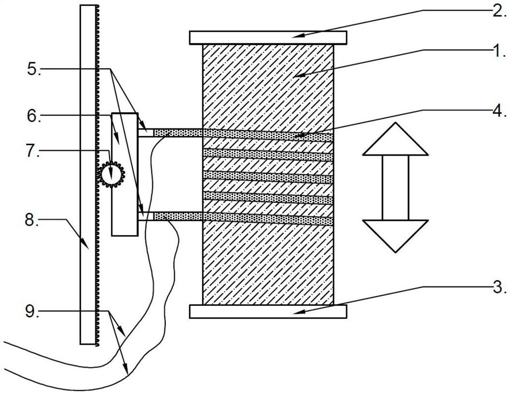
[0022] figure 1 It is a schematic diagram of an inductively coupled radio frequency ion source with an adjustable coil position. Such as figure 1 As shown, the coil position adjustable inductively coupled RF ion source includes a discharge chamber 1, an upper transition flange 2, a lower transition flange 3, a coupling coil 4, an insulating component 5, a coil support 6, a stepping motor and a gear set 7, Slide rail 8, flexible cable 9, radio frequency power source and impedance matching network, etc. Plasma is mainly generated in the dischar...
PUM
 Abstract
Description
Claims
Application Information
 - Generate Ideas
- Intellectual Property
- Life Sciences
- Materials
- Tech Scout
- Unparalleled Data Quality
- Higher Quality Content
- 60% Fewer Hallucinations
Browse by: Latest US Patents, China's latest patents, Technical Efficacy Thesaurus, Application Domain, Technology Topic, Popular Technical Reports.
© 2025 PatSnap. All rights reserved.Legal|Privacy policy|Modern Slavery Act Transparency Statement|Sitemap|About US| Contact US: help@patsnap.com