An electric switchgear for low-voltage and medium-voltage applications

A technology for electrical switches and equipment, which is applied to electrical equipment enclosures/cabinets/drawers, switchgears with horizontal pull isolation, electrical components, etc., and can solve problems such as danger to operators and damage to internal components of switchgear

Pending Publication Date: 2021-09-17
ABB (SCHWEIZ) AG
View PDF0 Cites 0 Cited by
  • Summary
  • Abstract
  • Description
  • Claims
  • Application Information

AI Technical Summary

Problems solved by technology

These phenomena can cause associated damage to the internal components of the switchgear and can be extremely dangerous for operating personnel

Method used


Image

  • An electric switchgear for low-voltage and medium-voltage applications
  • An electric switchgear for low-voltage and medium-voltage applications
  • An electric switchgear for low-voltage and medium-voltage applications

Examples


Embodiment Construction

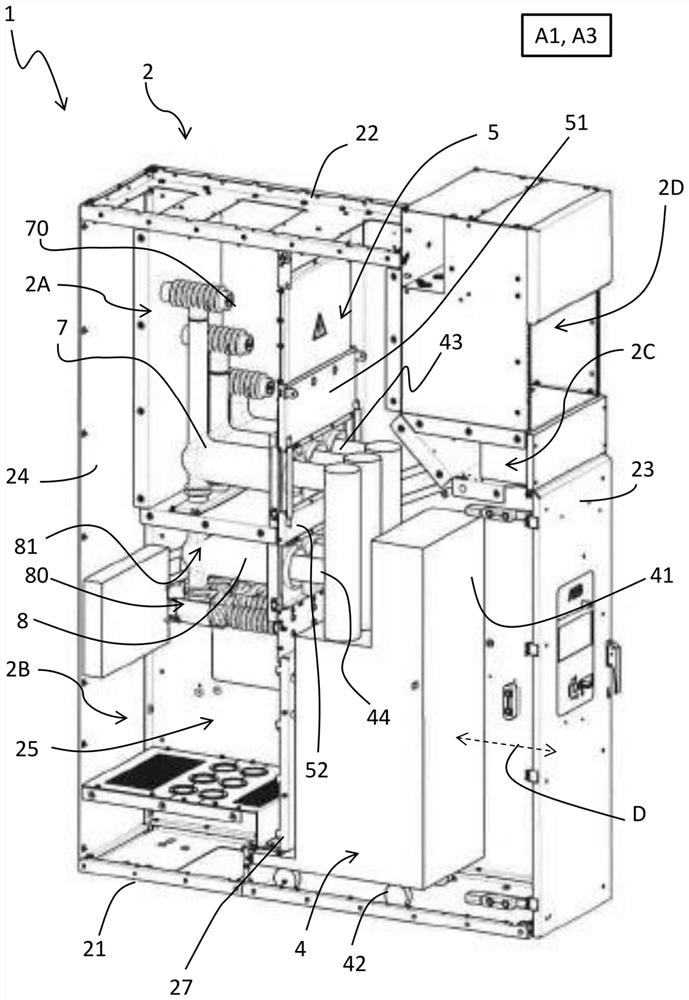
[0052]With reference to the above figures, the present invention relates to an electrical switching apparatus 1 for low or medium voltage applications.

[0053] For the purposes of the present invention, the term "low voltage" (LV) relates to operating voltages below 1 kV AC and 1.5 kV DC, while the term "medium voltage" (MV) relates to operating voltages above 1 kV up to a few tens of kV (for example, 70 kV AC and 100kV DC) working voltage.

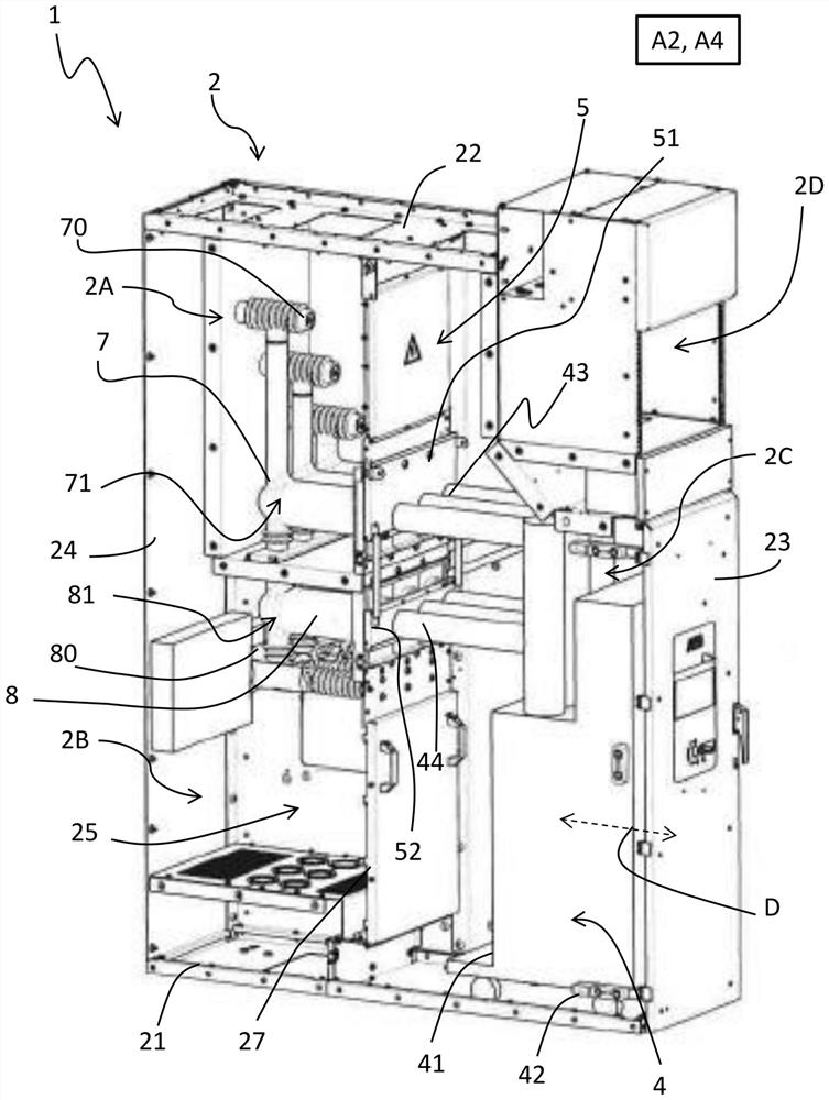
[0054] The switchgear 1 comprises a cabinet 2 comprising a plurality of walls 21, 22, 23, 24, 25 defining an internal volume.

[0055] Referring to the normal installation position, the cabinet 2 includes a horizontal base wall 21, a horizontal top wall 22 in an opposite position relative to the horizontal base wall 21, and a plurality of vertical walls ( Figure 1-2 ).

[0056] These vertical walls include: a front wall 23 from which an operator can access the interior volume of the cabinet; a rear wall 24 in an opposite position with ...


PUM


Abstract

An electric switchgear for low-voltage or medium-voltage applications comprises a cabinet, a withdrawable switching apparatus and a shutter assembly movable along a reference plane of motion. The electric switchgear comprises one or more power connection blocks comprising a line contact, a disconnection contact and an insulating casing. According to the electric switchgear, at least said line contact and said insulating casing form a monolithic structure.

Description

technical field [0001] The invention relates to an electrical switchgear for low or medium voltage applications. [0002] More particularly, the present invention relates to an electrical switching apparatus comprising a withdrawable switching device and having an improved power connection block for electrical connection to a conductor of an electrical line. Background technique [0003] Electrical switchgear is well known in electrical power transmission and distribution networks. [0004] Known electrical switchgear generally comprises a metal cabinet internally divided into several compartments or units accommodating various devices and equipment. [0005] In many applications, electrical switching apparatus includes switching devices of the withdrawable type (such as circuit breakers), that is, such switching devices are reversibly movable between a first position (inserted position) and a second position (drawn position), in which In the first position the switching d...

Claims


Application Information

Patent Timeline
IPC IPC(8): H05K5/02
CPCH05K5/0217H05K5/0247H02B11/04H02B11/12
Inventor F·佩拉齐A·阿瓦提
Owner ABB (SCHWEIZ) AG
Why Eureka
Try Eureka