Dual-motor transmission structure, driving system and electric engineering vehicle

A transmission structure, dual-motor technology, applied in electric vehicles, control drives, vehicle components, etc., can solve the problems of complex power coupling implementation and shifting control, difficult to develop electric engineering vehicles, and difficult to electric engineering machinery, etc. Economy and reliability, low cost, space saving effect

Inactive Publication Date: 2021-09-21
JIANGSU ADVANCED CONSTR MASCH INNOVATION CENT LTD
View PDF5 Cites 0 Cited by
  • Summary
  • Abstract
  • Description
  • Claims
  • Application Information

AI Technical Summary

Problems solved by technology

[0003] In the prior art, several patents have proposed a dual-input, single-output power coupling system. Although such a system can be applied to a carrier vehicle with a single drive configuration, it is difficult to directly meet high-speed transition and low-speed high-torque operations. Electric construction machinery, and the realization of power coupling and shift control are complicated, the development cost is high, and power interruption will occur during the shift process, so it is difficult to apply to the development of electric construction vehicles

Method used


Image

  • Dual-motor transmission structure, driving system and electric engineering vehicle
  • Dual-motor transmission structure, driving system and electric engineering vehicle
  • Dual-motor transmission structure, driving system and electric engineering vehicle

Examples


Embodiment 1

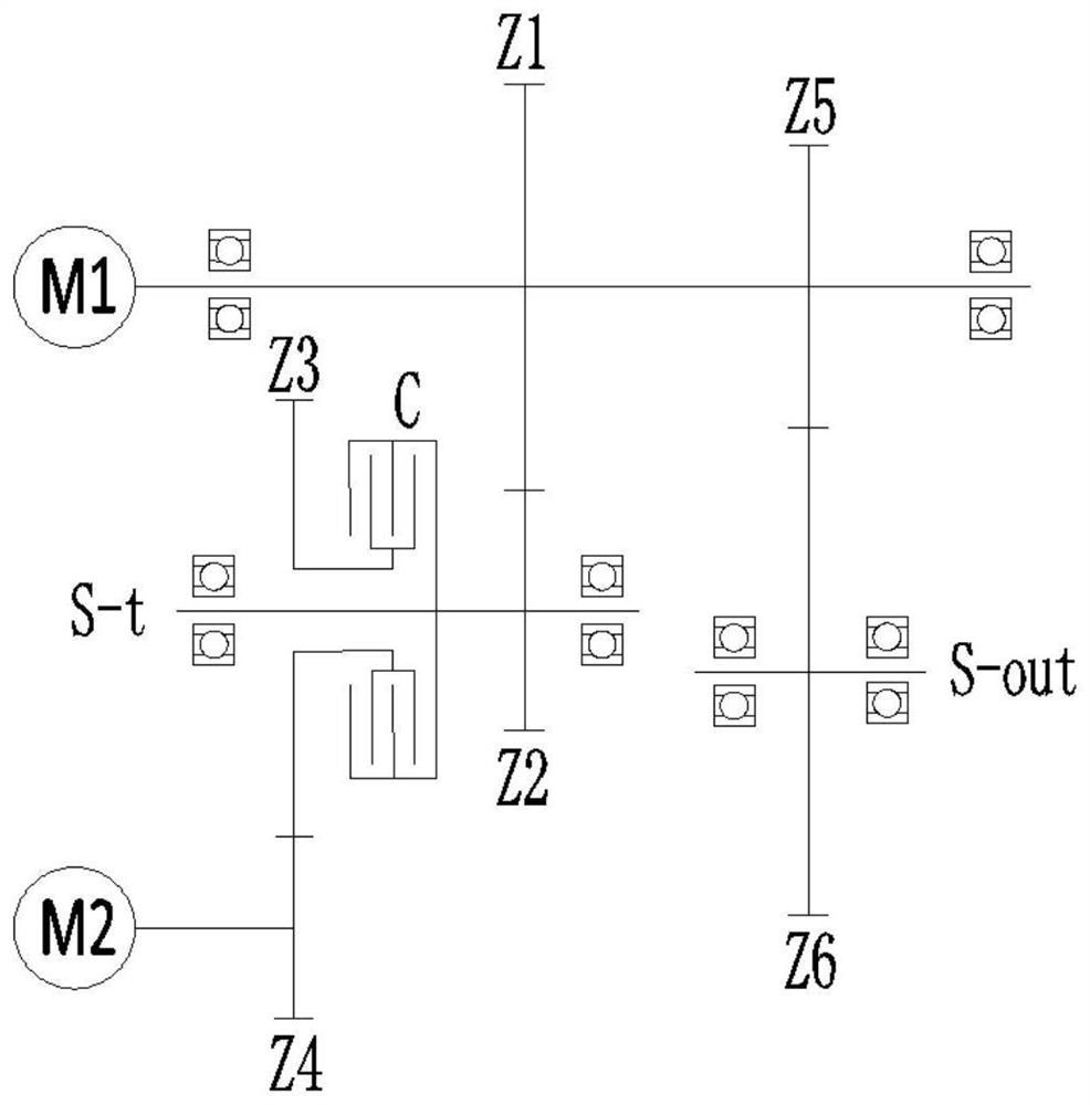
[0030] See attached figure 1 , a dual-motor transmission structure, including a first motor M1, a second motor M2, a power coupling transmission unit, a walking driving force transmission unit, and a walking driving force output shaft S-out, and the power coupling transmission unit is transmission-connected to the first motor M1 Between the output shaft of the first motor M1 and the output shaft of the second motor M2, the power coupling transmission unit includes a coupling clutch C, and the travel driving force transmission unit is connected between the output shaft of the first motor M1 and the travel driving force output shaft S-out, The walking driving force output shaft S-out is equipped with a walking driving force output end;

[0031] The transmission structure realizes the independent drive mode and the coupled drive mode, wherein:

[0032] Single drive mode: including the first motor M1 single drive mode and the second motor M2 single drive mode; in the first motor ...

Embodiment 2

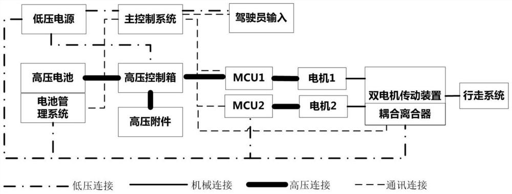
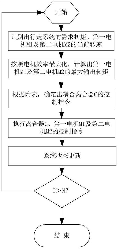
[0039] See attached figure 2 And attached image 3 , a dual-motor drive system, including any of the above-mentioned dual-motor transmission structures, and also includes a driver operation input terminal, a low-voltage power supply, a power source, and a main control system, the signal of the driver operation input terminal is connected to the main control system, and the low-voltage power supply Provide power for the main control system, the power source provides power for the first motor M1, and the low-voltage power supply provides power for the second motor M2, and the main control system executes the following control process:

[0040] a. According to the driver's operation input terminal information and vehicle state information, identify the torque required for the current required walking state and the current speed of the first motor M1 and the second motor M2;

[0041] b. Based on the principle of maximizing motor efficiency, calculate the maximum output torque of...

Embodiment 3

[0046] See attached figure 2 , an electric engineering vehicle, including the above-mentioned dual-motor drive system, and also includes a walking system, the walking driving force output shaft S-out is connected to the walking system, and the first motor M1 and the second motor M2 are coupled and controlled by the main control system Power output, to complete the required form function.

[0047] Compared with the prior art, the advantages of the dual-motor transmission structure, drive system and electric engineering vehicle of the embodiment of the present invention are: the dual-motor drive system in the embodiment of the present invention, compared with the planetary transmission form, does not need to shift gears in the middle to ensure no For power interruption, only one clutch needs to be controlled to achieve power coupling. At the same time, according to the requirements of the working conditions, the torque of the two motors can be reasonably distributed, the contro...


PUM


Abstract

The invention relates to a dual-motor transmission structure, which comprises a first motor M1, a second motor M2, a power coupling transmission unit, a walking driving force transmission unit and a walking driving force output shaft S-out, and is characterized in that the power coupling transmission unit is in transmission connection between an output shaft of the first motor M1 and an output shaft of the second motor M2; a walking driving force output end is arranged on the walking driving force output shaft S-out; the driving system controls power output in a coupling mode through the main control system and is used for driving a walking system in the electric engineering vehicle, the needed vehicle state is achieved, the flexible characteristic of double-motor control is utilized, gearbox gear shifting is omitted, the working condition requirement for high-speed transition of the engineering vehicle is met, the economical efficiency and reliability of the whole vehicle are improved, and the driving system is simple in structure control and low in cost, power interruption is avoided; the whole vehicle is more compact in arrangement, space is saved, the motor often works in a high-efficiency interval, the overload working condition is few, and the service life of the motor is prolonged.

Description

technical field [0001] The invention relates to the technical field of electric engineering vehicles, in particular to a dual-motor transmission structure and an engineering vehicle. Background technique [0002] In order to meet the continuous improvement of construction operation efficiency and the requirements of environmental protection, construction machinery is gradually developing in the direction of electrification. The current configuration of the construction machinery walking system directly replaces the engine with a single motor, retains the original gearbox as the power source, and does not take advantage of the wide torque and speed of the motor, resulting in a single motor that will keep the motor in the low-efficiency torque area for a long time At the same time, it is difficult to coordinate the gear shift strategy of the gearbox and the motor, and the economy of the whole vehicle is poor. Taking the typical electric construction machinery of loader as an ...

Claims


Application Information

Patent Timeline
Patent Type & Authority Applications(China)
IPC IPC(8): B60K17/00B60K17/02B60K1/02B60L15/20
CPCB60K17/00B60K17/02B60K1/02B60L15/2054Y02T10/72
Inventor 薛卡詹东安户丹丹邵杏国梁岩岩
Owner JIANGSU ADVANCED CONSTR MASCH INNOVATION CENT LTD
Why Eureka
Try Eureka