Random trigger control method, random trigger control system and laser system
A technology of triggering control and laser module, applied in the field of control, can solve the problems of chaotic light output, limit the frequency of TRIG signal, lost points, etc., to achieve the effect of ensuring consistency
- Summary
- Abstract
- Description
- Claims
- Application Information
AI Technical Summary
Problems solved by technology
Method used
Image

Examples
Embodiment 1
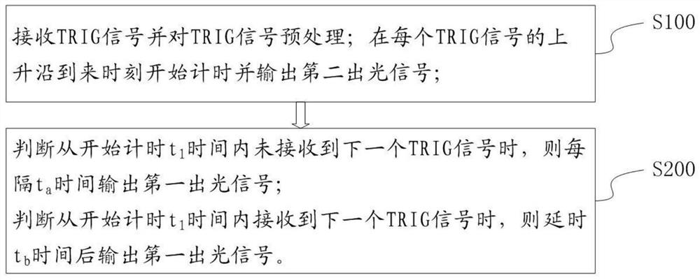
[0034] Please refer to figure 1 A flow chart of a random trigger control method provided by this application, including the following steps:
[0035] S100: Receive a TRIG signal and preprocess the TRIG signal; start timing when each rising edge of the TRIG signal arrives and output a second light output signal;
[0036] S200: judging from the start of timing t 1 When the next TRIG signal is not received within the time, every t a Time to output the first light signal;
[0037] Judging from the start timing t 1 When the next TRIG signal is received within time, delay t b After a certain time, the first output light signal is output.
[0038] Those skilled in the art can know that the TRIG signal is an external trigger signal. For example, the TRIG interface adopts the signal edge trigger mode to realize the light output control of the laser;
[0039] The first optical signal can be used to turn on the primary optical fiber modulator of the laser, and the second optical si...
Embodiment 2
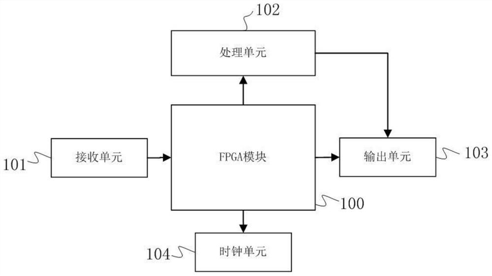
[0057] This embodiment provides a random trigger control system, such as figure 2 As shown, the FPGA module 100 is included; the FPGA module 100 includes a receiving unit 101, a processing unit 102, an output unit 103 and a clock unit 104;
[0058] The receiving unit 101 is configured to receive a TRIG signal;
[0059] The output unit 103 is configured to output a first optical signal and a second optical signal;
[0060] The clock unit 104 is configured to start timing and output clock data when each rising edge of the TRIG signal arrives; the clock data includes start timing information and timing time;
[0061] The processing unit 102 is configured to: preprocess the TRIG signal; acquire clock data; when the timing start information is acquired, control the output unit 103 to output a second light output signal; determine that the timing time is greater than t 1 , then control the output unit 103 every t a Time to output the first light output signal; judging that the ...
Embodiment 3
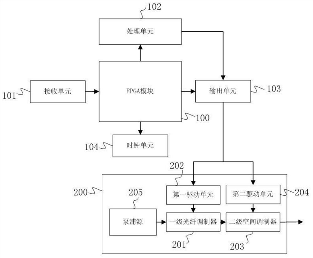
[0073] This embodiment provides a laser system, such as image 3 As shown, it includes a laser module 200 and a random trigger control system as described above;
[0074] The laser module 200 includes a primary fiber modulator 201, a first drive unit 202; a secondary spatial modulator 203, a second drive unit 204; and a pump source 205;
[0075] The first drive unit 202 is used to receive the first light output signal and control the primary fiber modulator 201 to turn on; the second drive unit 204 is used to receive the second light output signal and control the secondary The spatial modulator 203 is turned on;
[0076] The pumping source 205 is used to output signal light, and the signal light outputs laser light after passing through the primary optical fiber modulator 201 and the secondary spatial modulator 203 .
[0077] working principle:
[0078] When the receiving unit 101 acquires an external TRIG signal, it sends it to the processing unit 101, and the processing u...
PUM
 Abstract
Description
Claims
Application Information
 - R&D
- Intellectual Property
- Life Sciences
- Materials
- Tech Scout
- Unparalleled Data Quality
- Higher Quality Content
- 60% Fewer Hallucinations
Browse by: Latest US Patents, China's latest patents, Technical Efficacy Thesaurus, Application Domain, Technology Topic, Popular Technical Reports.
© 2025 PatSnap. All rights reserved.Legal|Privacy policy|Modern Slavery Act Transparency Statement|Sitemap|About US| Contact US: help@patsnap.com