
Error-eliminating double-cylindrical-mirror astigmatism-correcting device and subjective and objective optometry unit

A cylindrical mirror and double-cylinder technology, which is applied in the field of high-precision optometry devices, can solve the problems that the cylindrical mirror cannot be in the position of the conjugate plane of the pupil at the same time, the large error of the astigmatism value, the error, etc., and achieve accurate objective and subjective measurement results. , The diopter measurement is fast and accurate, and the connection design is reasonable.

Inactive Publication Date: 2021-09-24
陈奎
View PDF3 Cites 0 Cited by
  • Summary
  • Abstract
  • Description
  • Claims
  • Application Information

AI Technical Summary

Problems solved by technology

[0003] Chinese patent CN201610303646.6 introduces an optometry method of a comprehensive refractometer. The patient's diopter needs to be measured in advance on an objective refractometer, and then moved to the comprehensive refractometer, and the combined lens generates the corresponding degree to complete the comprehensive optometry. In this optometry process, objective optometry obtains continuous refractive errors, but subjective optometry can only select test lenses step by step, and the differences between them affect the accuracy of optometry; and astigmatism lenses have directionality, and their angle tolerance is small, and operation is difficult. The angle error will affect the accuracy of optometry when inserting the film manually
However, in this patent, there are two separated but overlapping cylindrical mirrors near the position conjugated to the pupil of the tested human eye. Since the cylindrical mirrors have thickness, the two cylindrical mirrors Can not be in the position of the same conjugate surface at the same time, no matter one cylindrical mirror is in the position of the conjugate surface, the other cylindrical mirror is not in the position of the conjugate surface, or the two cylindrical mirrors are respectively located on the two sides of the conjugate surface On the technical side, there is a technical defect that the two cylindrical mirrors cannot be at the position of the pupil conjugate plane at the same time. As a result, there is an error between the synthetic astigmatism produced by the two cylindrical mirrors and the astigmatism that needs to be corrected. The larger the astigmatism value The greater the error

Method used


Image

  • Error-eliminating double-cylindrical-mirror astigmatism-correcting device and subjective and objective optometry unit
  • Error-eliminating double-cylindrical-mirror astigmatism-correcting device and subjective and objective optometry unit

Examples


Embodiment 1

[0036] Embodiment 1. Eliminate the device for correcting astigmatism error by double cylinder mirrors

[0037] Such as figure 1 with 2 .

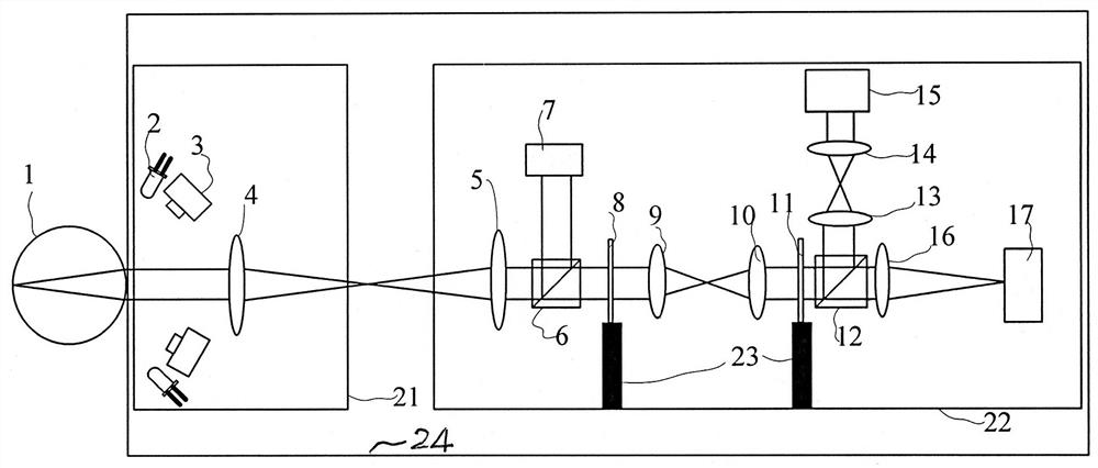
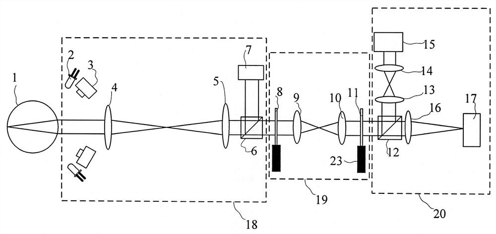
[0038] [1] The structure of the device for correcting astigmatism: it includes two cylindrical mirrors and two convex lenses, and is characterized in that the first cylindrical mirror 8, the first convex lens 9, the second convex lens 10, and the second cylindrical Surface mirror 11, wherein the first convex lens 9 and the second convex lens 10 form the structure of a 4f system; the direction of the first cylindrical mirror 8, the first convex lens 9, the second convex lens 10, and the second cylindrical mirror 11 remains fixed The interval position; the first cylindrical lens 8 is located at the focal plane position of the first convex lens 9, and the second cylindrical lens 11 is located at the focal plane position of the second convex lens 10; the refractive correction frame is also provided with a cylindrical lens driver 23, The two ...

Embodiment 2

[0047] Embodiment 2, Eliminate the device for correcting astigmatism error by double cylinder mirror

[0048] Such as figure 1 , 2 ,

[0049] [1] The structure of the device for correcting astigmatism: the same as in Embodiment 1.

[0050] [2] The parameters of the components are selected as follows:

[0051] The first cylindrical mirror 8 selects -5D;

[0052] The first convex lens 9 selects +20D for use;

[0053] The second convex lens 10 selects +20D for use;

[0054] The second cylindrical mirror 11 selects -5D;

[0055] The range of synthetic astigmatism that can be produced by the first cylindrical lens 8 and the second cylindrical lens 11 is -10D to +10D.

[0056] The position settings of the first cylindrical lens 8, the first convex lens 9, the second convex lens 10, and the second cylindrical lens 11 meet the 4f system setting in geometrical optics, so that the first convex lens 9 and the second convex lens 10 become a relay optical path .

Embodiment 3

[0057] Embodiment 3, device for eliminating astigmatism error corrected by double cylinder mirror

[0058] Such as figure 1 , 2 ,

[0059] [1] The structure of the device for correcting astigmatism: the same as in Embodiment 1.

[0060] [2] The parameters of the components are selected as follows:

[0061] The first cylindrical mirror 8 selects +5D;

[0062] The first convex lens 9 selects +20D for use;

[0063] The second convex lens 10 selects +20D for use;

[0064] The second cylindrical mirror 11 selects -5D;

[0065] The range of synthetic astigmatism that can be produced by the first cylindrical lens 8 and the second cylindrical lens 11 is -10D to +10D.

[0066] The position settings of the first cylindrical lens 8, the first convex lens 9, the second convex lens 10, and the second cylindrical lens 11 meet the 4f system setting in geometrical optics, so that the first convex lens 9 and the second convex lens 10 become a relay optical path .


PUM


Abstract

The invention discloses an error-eliminating double-cylindrical-mirror astigmatism-correcting device and a subjective and objective optometry unit and relates to an ophthalmology optometry device for high-precision subjective and objective examination. In the error-eliminating double-cylindrical-mirror astigmatism-correcting device, two cylindrical mirrors are placed on a focal plane of a 4f system composed of two convex lenses respectively. Astigmatism is corrected through rotation of the two cylindrical mirrors along an optical axis; and a main optical path and two branch optical paths for subjective and objective optometry are reasonably arranged by the optometry unit. The optometry unit has advantages that an image judgment device for three-dimensional positioning of eyes and objective and subjective diopter measurements are combined into the optometry unit, a technical problem that the two cylindrical mirrors are arranged on a conjugate surface at the same time to eliminate errors is solved through a two-pupil equivalent conjugate surface structure, and diopter measurement is rapid and correction is accurate. A communication design of the main optical path and the two branch optical paths is reasonable, channel paths of the branch optical paths are short, and due to the fact that errors generated by the branch optical paths are small, objective and subjective measurement results obtained by the optometry unit are more accurate.

Description

technical field [0001] The invention relates to the technical field of optical measurement used in ophthalmology, in particular to a high-precision optometry device for subjective and objective measurement. Background technique [0002] At present, the commonly used clinical refractometer mainly includes combined lenses and eye charts. When people carry out optometry, the routine process is to first obtain the diopters of the left and right eyes through ophthalmoscope or objective refractometer, and then use the comprehensive refractometer according to the measurement. The obtained diopter of the patient is simulated to wear, and the optometrist issues an adjustment command to correct the simulated wearing degree until the correction is the best for the patient's subjective experience. [0003] Chinese patent CN201610303646.6 introduces an optometry method of a comprehensive refractometer. The patient's diopter needs to be measured in advance on an objective refractometer, a...

Claims


Application Information

Patent Timeline
Patent Type & Authority Applications(China)
IPC IPC(8): A61B3/00A61B3/032A61B3/036A61B3/103A61B3/14A61F9/00
CPCA61B3/0016A61B3/032A61B3/036A61B3/103A61B3/1035A61B3/14A61B3/0008A61F9/00
Inventor 陈奎
Owner 陈奎
Learn More