
A low-loss cutting machine

A cutting machine, low-loss technology, used in forming/shaping machines, special forming/shaping machines, manufacturing tools, etc., can solve problems such as easy scratching of human hands, easy deformation of saw teeth, and increase in production costs of enterprises. The probability of injury, the possibility of reducing the deformation, the effect of ensuring the flatness

Active Publication Date: 2022-07-22
天津市众达精工精密机械有限公司
View PDF0 Cites 0 Cited by
  • Summary
  • Abstract
  • Description
  • Claims
  • Application Information

AI Technical Summary

Problems solved by technology

[0003] In the prior art, the cutting of the wooden board also needs to be completed by a cutting machine, but in the prior art, a sawtooth-shaped cutting machine is usually used to cut the wooden board. Afterwards, the edge of the wooden board will be full of sharp burrs, which are very easy to scratch the hands. At the same time, the saw teeth are prone to deformation after a long period of use. The cutting efficiency of the saw gear will be greatly reduced

Method used


Image

  • A low-loss cutting machine
  • A low-loss cutting machine
  • A low-loss cutting machine

Examples


Embodiment Construction

[0023] use Figure 1-Figure 7 A low-loss cutter according to an embodiment of the present invention will be described below.

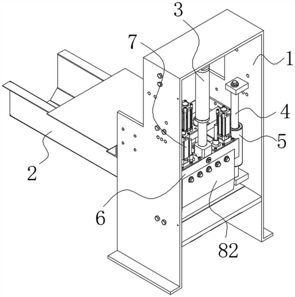
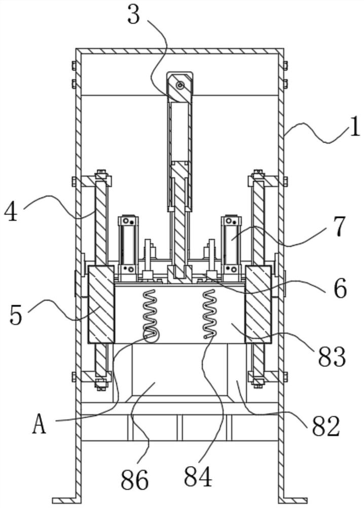
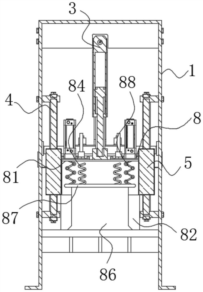
[0024] like Figure 1-Figure 7As shown, a low-loss cutting machine according to the present invention includes a mounting frame 1, a conveying track 2, a hydraulic cylinder 3, a sliding rod 4, a sleeve 5, an outer plate 6, a level 7 and a cutting mechanism 8; the installation The inner lower end of the frame 1 is fixedly connected with the conveying track 2 by screws, and the inner upper wall of the mounting frame 1 is fixedly connected with a hydraulic cylinder 3; the lower end of the hydraulic cylinder 3 is slidably connected to the middle wall of the outer plate 6; The two ends of the plate 6 are fixedly connected to the inner surface of the sleeve 5; the sleeve 5 is slidably connected to the outer wall of the sliding rod 4; Levels 7 are slidably connected to both end walls of the outer plate 6 , and a cutting mechanism 8 is arranged on the lower ...


PUM


Abstract

The invention belongs to the technical field of cutting devices, in particular to a low-loss cutting machine, comprising a mounting frame, a conveying track, a hydraulic cylinder, a sliding rod, a casing, an outer plate, a level and a cutting mechanism; The conveying track is fixedly connected by screws, and the inner upper wall of the mounting frame is fixedly connected with a hydraulic cylinder; the lower end of the hydraulic cylinder is slidably connected to the middle wall of the outer plate; the two ends of the outer plate are fixedly connected to the casing The inner surface; the sleeve is slidably sleeved on the outer wall of the sliding rod; the sliding rod is symmetrically fixed and connected to the inner two ends of the mounting frame by screws; Therefore, when the guide wheel rotates, the dust remaining on the outer surface of the guide wheel can be scraped off by the scraper, so that the high friction force between the guide wheel and the connecting rod is always maintained, and the protection of the guide wheel is further improved.

Description

technical field [0001] The invention belongs to the technical field of cutting devices, in particular to a low-loss cutting machine. Background technique [0002] With the development of modern mechanical processing industry, the requirements for cutting quality and precision are constantly improving, and the requirements for improving production efficiency, reducing production costs, and having highly intelligent automatic cutting functions are also increasing. The development of CNC cutting machine must meet the requirements of the development of modern mechanical processing industry. Cutting machines are divided into flame cutting machines, plasma cutting machines, laser cutting machines, water cutting machines, etc. The laser cutting machine is the fastest in efficiency, the highest in cutting accuracy, and the cutting thickness is generally small. The cutting speed of the plasma cutting machine is also very fast, and the cutting surface has a certain slope. The flame...

Claims


Application Information

Patent Timeline
Patent Type & Authority Patents(China)
IPC IPC(8): B27C5/02B27C5/06B27G3/00B27G21/00
CPCB27C5/006B27C5/02B27C5/06B27G3/00B27G21/00
Inventor 许雪芬
Owner 天津市众达精工精密机械有限公司
Learn More