
A carburizing and quenching segmented heat treatment system based on transmission shaft and its treatment method

A heat treatment system, carburizing and quenching technology, applied in heat treatment furnaces, heat treatment equipment, heat treatment process control, etc., can solve the problems of difficulty in achieving local quenching of the transmission shaft at the same time, difficult to accurately control the heating temperature, and inconvenient in taking and placing the transmission shaft. Improve heat treatment efficiency, facilitate operation, and ensure the effect of quenching quality

Active Publication Date: 2022-08-09
斯捷尔传动机械(杭州)有限公司
View PDF10 Cites 0 Cited by
  • Summary
  • Abstract
  • Description
  • Claims
  • Application Information

AI Technical Summary

Problems solved by technology

[0007] Aiming at the deficiencies of the prior art, the present invention provides a transmission shaft-based carburizing and quenching segmental heat treatment system and its treatment method, which solves the problem that the surface of the transmission shaft is not subjected to segmental heat treatment in advance, and the heating temperature is difficult to control accurately. In the heat treatment process, the waste heat is not fully utilized, which increases energy consumption, makes it difficult to pick and place the stacked drive shafts, and is difficult to achieve local quenching of the drive shafts at the same time

Method used


Image

  • A carburizing and quenching segmented heat treatment system based on transmission shaft and its treatment method
  • A carburizing and quenching segmented heat treatment system based on transmission shaft and its treatment method
  • A carburizing and quenching segmented heat treatment system based on transmission shaft and its treatment method

Examples


Embodiment Construction

[0043] The technical solutions in the embodiments of the present invention will be clearly and completely described below with reference to the accompanying drawings in the embodiments of the present invention. Obviously, the described embodiments are only a part of the embodiments of the present invention, but not all of the embodiments. Based on the embodiments of the present invention, all other embodiments obtained by those of ordinary skill in the art without creative efforts shall fall within the protection scope of the present invention.

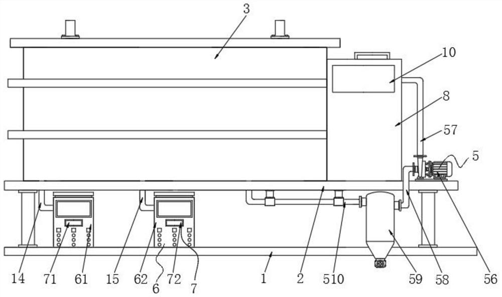
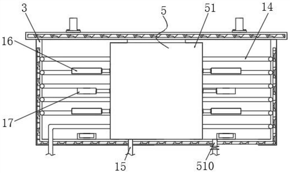
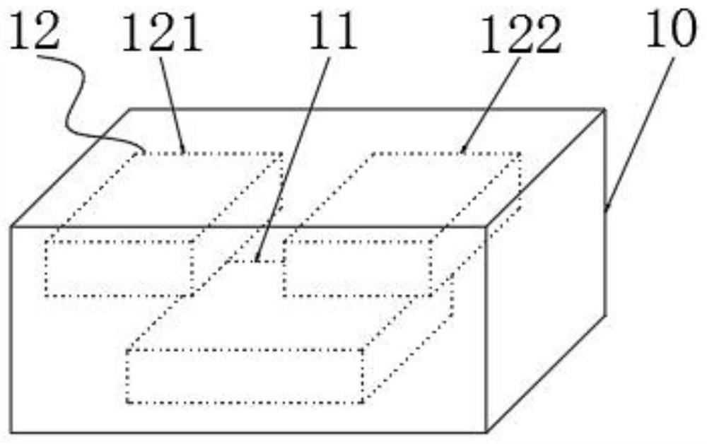
[0044] see Figure 1-10 , the embodiment of the present invention provides a technical solution: a carburizing and quenching segmented heat treatment system based on a transmission shaft, comprising a base plate 1 and a support frame 2 fixedly connected to the top of the base plate 1 through support legs, and one side of the top of the support frame 2 The heating box 3 is fixedly connected, and the bottom of the inner wall of the heat...


PUM


Abstract

The present invention disclosed a carbonic quenching segmentation thermal treatment system and its treatment method based on the drive shaft, including the bottom plate and the supporting frame connected to the top of the bottom plate by supporting the legs.Inventory involves the field of transmission axis thermal treatment technology.This transmission shaft -based carburizing quenching segmented thermal treatment system and its treatment method. By performing segmented preheating and heating treatment on the transmission shaft during quenching, the temperature range of the temperature during quenching can be accurately controlled to ensure the quenching quality of the transmission shaftAt the same time, use the waste heat collection agency to collect the transmission shaft and collect the remaining heat generated during cooling and transport it to the inside of the heating box to facilitate the heat treatment of the subsequent transmission shaft, save power energy consumption, meet the needs of energy saving and environmental protection.The settings can be stabilized for multiple transmission shafts, and after quenching and preheating, they can be uniformly obtained, which reduces the work intensity of personnel.

Description

technical field [0001] The invention relates to the technical field of heat treatment of transmission shafts, in particular to a carburizing and quenching subsection heat treatment system based on transmission shafts and a processing method thereof. Background technique [0002] The drive shaft is a rotating body with high speed and few supports, so its dynamic balance is very important. Generally, the drive shaft must be tested for dynamic balance before leaving the factory, and adjusted on the balancing machine. For a wheel-driven car, it is the shaft that transmits the rotation of the transmission to the main reducer. It can have several sections, and the joints can be connected by universal joints. Its function is to transmit the power of the engine to the wheels together with the gearbox and the drive axle, so that the car can generate driving force. [0003] With reference to a heat treatment device for machine tool spindle production with reference to Chinese Patent ...

Claims


Application Information

Patent Timeline
Patent Type & Authority Patents(China)
IPC IPC(8): C21D9/28C21D11/00C21D1/18C21D1/10C21D1/63C23C8/00
CPCC21D9/28C21D11/00C21D9/0062C21D9/0006C21D1/18C21D1/10C21D1/63C23C8/00Y02P10/25
Inventor 赵国柱
Owner 斯捷尔传动机械(杭州)有限公司
Learn More