Novel wood composite floor
A composite floor and wood technology, applied in the direction of floors, insulation layers, buildings, etc., can solve the problems of crack resistance, poor toughness, no technical solutions, and easy cracking of wood grain paper, etc., to achieve good crack resistance Cracking and toughness, and the effect of improving the bonding strength
- Summary
- Abstract
- Description
- Claims
- Application Information
AI Technical Summary
Problems solved by technology
Method used
Image

Examples
Embodiment 1
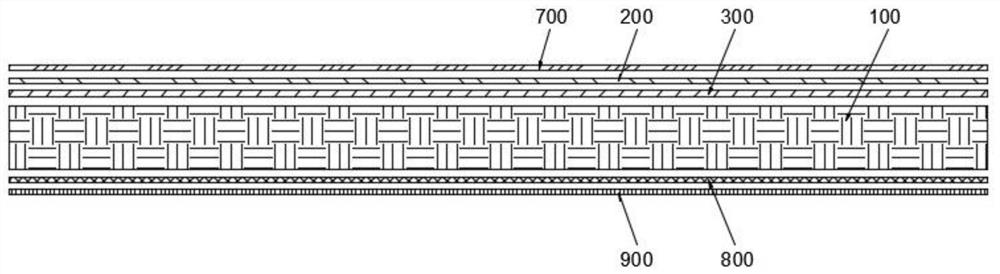
[0027] Example 1: Reference figure 1 A new wood composite floor is shown, which includes a wear-resistant layer 700, a wood grain paper layer 200, a fiber paper layer 300, a wooden substrate layer 100, a back decoration layer 800 and a transparent moisture-proof layer 900 from the surface to the bottom. Wherein, the wear-resistant layer 700 is any kind of wear-resistant paper in the prior art, such as Al2O3 impregnated paper; the wood grain paper layer 200 is any kind of decorative paper in the prior art; the fiber used in the fiber paper layer 300 The paper is melamine-impregnated fiber paper; the wooden substrate layer 100 can be any kind of wooden composite substrate, such as multi-layer solid wood composite substrate; the back decoration layer 800 can be any kind, such as decorative paper or fast-growing wood veneer; transparent The moisture-proof layer 900 can be any kind, such as pvc coating.
[0028] By sticking the fiber paper layer 300 between the wood substrate laye...
Embodiment 2
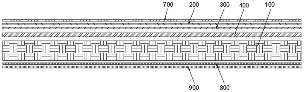
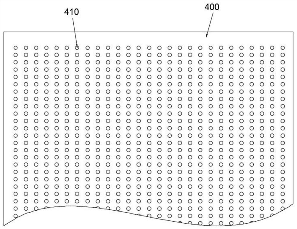
[0030] Embodiment 2: the difference between embodiment 2 and embodiment 1 is that, refer to figure 2 , image 3 As shown, a high-density fiberboard layer 400 is glued between the fiber paper layer 300 and the wood substrate layer 100 . In this embodiment, the thickness of the high-density fiberboard used in the high-density fiberboard layer 400 is 0.8 mm to 1.2 mm, and the density is 0.9 kg / m 3 ~1.2kg / m 3 , preferred thickness 1.0mm, preferred density 1.0kg / m 3 .
[0031] Through the setting of the high-density fiberboard layer 400, the wood grain paper layer 200 and the fiber paper layer 300 have a relatively flat sticking plane, so as to avoid to a certain extent due to the wood substrate layer 100 (originally having or caused by deformation) ) surface unevenness (especially multi-layer solid wood composite substrate) and form fine wrinkles on the wood grain paper layer 200, fiber paper layer 300, and affect the quality of product surface flatness.
[0032] Those of or...
Embodiment 3
[0034] Embodiment 3: the difference between embodiment 3 and embodiment 1 is that, refer to Figure 4As shown, a first balancing paper layer 500 is glued between the high-density fiberboard layer 400 and the wooden substrate layer 100 , and a second balancing paper layer 600 is glued on the back of the wooden substrate layer 100 . The first balancing paper layer 500 is 60 g melamine impregnated paper and the second balancing paper layer 600 is 120 g melamine impregnated paper.
PUM
| Property | Measurement | Unit |
|---|---|---|
| thickness | aaaaa | aaaaa |
| density | aaaaa | aaaaa |
| pore size | aaaaa | aaaaa |
Abstract
Description
Claims
Application Information
 - R&D
- Intellectual Property
- Life Sciences
- Materials
- Tech Scout
- Unparalleled Data Quality
- Higher Quality Content
- 60% Fewer Hallucinations
Browse by: Latest US Patents, China's latest patents, Technical Efficacy Thesaurus, Application Domain, Technology Topic, Popular Technical Reports.
© 2025 PatSnap. All rights reserved.Legal|Privacy policy|Modern Slavery Act Transparency Statement|Sitemap|About US| Contact US: help@patsnap.com