Lithium niobate integrated MZI type optical waveguide large-current sensor and measuring system

A measurement system and optical waveguide technology, applied in measurement devices, measuring only current, measuring electrical variables, etc., can solve the problems of unsolved magnetic saturation, environmental magnetic field, birefringence of optical fiber sensing coils, unstable sensor operation, etc. Improve integration and stability, fast response time, and avoid the effect of energy radiation

Active Publication Date: 2021-09-24
BEIJING SENFU SCI & TECH CO LTD
View PDF6 Cites 0 Cited by
  • Summary
  • Abstract
  • Description
  • Claims
  • Application Information

AI Technical Summary

Problems solved by technology

The photoelectric hybrid sensor still uses the traditional electromagnetic induction principle, and the optical fiber is only used for signal transmission, and does not solve the influence of factors such as magnetic saturation and environmental magnetic field.
The all-fiber-optic current sensor also has a large change in the Verdet constant of the magneto-optical material due to the influence of temperature, which makes the sensor work very unstable and requires temperature compensation, and the optical fiber sensing coil used in the sensor also has a linear birefringence problem.
Although optical current sensors based on fiber Bragg gratings (FBG) and magnetostrictive materials overcome the problem of linear birefringence, the inherent temperature and strain cross-sensitivity of fiber gratings requires necessary temperature compensation.

Method used


Image

  • Lithium niobate integrated MZI type optical waveguide large-current sensor and measuring system
  • Lithium niobate integrated MZI type optical waveguide large-current sensor and measuring system
  • Lithium niobate integrated MZI type optical waveguide large-current sensor and measuring system

Examples


Embodiment Construction

[0039] The following will clearly and completely describe the technical solutions in the embodiments of the present invention with reference to the accompanying drawings in the embodiments of the present invention. Obviously, the described embodiments are only some, not all, embodiments of the present invention. Based on the embodiments of the present invention, all other embodiments obtained by persons of ordinary skill in the art without making creative efforts belong to the protection scope of the present invention.

[0040] In order to make the above objects, features and advantages of the present invention more comprehensible, the present invention will be further described in detail below in conjunction with the accompanying drawings and specific embodiments.

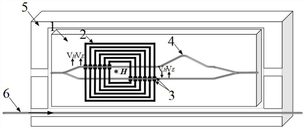
[0041] The invention provides a lithium niobate integrated MZI type optical waveguide high current sensor and measurement system, refer to figure 1 shown.

[0042] Such as figure 1As shown, the lithium niobate i...


PUM


Abstract

The invention discloses a lithium niobate integrated MZI type optical waveguide large-current sensor and a measuring system. The sensor comprises an x-cut y-pass lithium niobate wafer as a substrate of the lithium niobate integrated MZI type optical waveguide large-current sensor; and a multi-loop antenna which receives a magnetic field signal generated by a current-carrying wire to generate an induced current; wherein modulation electrodes and the multi-loop antenna are integrated on the asymmetric MZI optical waveguide. The left side and the right side of each loop of the multi-loop antenna are each provided with a pair of modulation electrodes. The asymmetric MZI optical waveguide is arranged on the x-cut y-pass lithium niobate wafer; the multi-loop antenna and the current-carrying wire are located on the same plane through the base, and the current-carrying wire is arranged on the side edge of the lithium niobate integrated MZI type optical waveguide large-current sensor. According to the invention, current measurement can be safely carried out under the condition of no contact with the measured current, energy radiation is avoided, the measurement efficiency is improved, the integration level and the stability of the sensor are greatly improved, and the complexity of the structure is reduced.

Description

technical field [0001] The invention relates to the field of optical current sensors, in particular to a lithium niobate integrated MZI type optical waveguide large current sensor and a measurement system. Background technique [0002] With the development of my country's power industry, the traditional power system is transforming into a modern power system. In enterprises and fields such as power companies, national defense and military industries, there are problems with the safe use of AC high current, DC high current and pulse high current generators, so high current measurement is essential in modern electrical systems. [0003] Shunts, current transformers and Rogowski coils are the traditional methods of current measurement. The resistance shunt method needs to be connected in series to the primary circuit, which makes installation inconvenient. There is no electrical isolation between the primary circuit and the secondary circuit, so it is not suitable for electroni...

Claims


Application Information

Patent Timeline
IPC IPC(8): G01R15/24G01R19/00
CPCG01R15/246G01R19/0092
Inventor 朱琨陆德坚张家洪陈福深
Owner BEIJING SENFU SCI & TECH CO LTD
Why Eureka
Try Eureka