Optical waveguide display device and AR display equipment

A display device and display device technology, applied in the direction of optical waveguide light guide, optical components, instruments, etc., can solve the problems of increasing the complexity of the optical path structure, unfavorable miniaturization of AR display equipment, etc., and achieve the effect of simplifying the optical path structure

Active Publication Date: 2021-09-24
LIGHTIN INC
View PDF6 Cites 5 Cited by
  • Summary
  • Abstract
  • Description
  • Claims
  • Application Information

AI Technical Summary

Problems solved by technology

[0003] However, based on the requirement that the AR display device finally needs to output color projection images, it is required that the light output by the lighting source of the projection light machine is a mixture of light waves of various colors into one beam In order to realize the mixing of different light rays and illuminate the projection chip, it is necessary to set up a relatively complex optical structure, which increases the complexity of the optical path structure to a certain extent, and is not conducive to the miniaturization of the overall AR display device.

Method used


Image

  • Optical waveguide display device and AR display equipment
  • Optical waveguide display device and AR display equipment
  • Optical waveguide display device and AR display equipment

Examples


Embodiment Construction

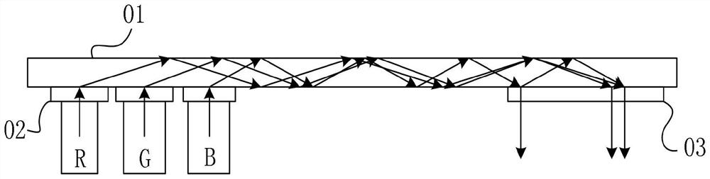
[0027] In a conventional AR display device, the projection light output by the projection light machine is generally a white light formed by mixing red, blue and green light, and the white light is coupled into the waveguide through the coupling grating reflected by the image chip to the waveguide , and is transmitted from one end of the in-coupling grating to one end of the out-coupling grating inside the waveguide and coupled out to the human eye through the diffraction effect of the out-coupling grating.

[0028] At present, there is no suitable solution for mass production of RGB chips. There are only three monochrome chips that output red, blue, and green light to mix into a bunch of white light to generate a color image. quite complicated. Therefore, in this application, it is conceived that the red, blue, and green light rays are not mixed before entering the waveguide, but are coupled into the waveguide through the three-color light beams respectively. In order to mak...


PUM


Abstract

The invention discloses an optical waveguide display device. The device comprises a waveguide element, a coupling-in grating and a coupling-out grating, wherein the coupling-in grating comprises a first diffraction grating, a second diffraction grating and a third diffraction grating which are arranged on the waveguide element in a non-fitting manner, and the first diffraction grating, the second diffraction grating and the third diffraction grating are respectively used for coupling light waves in different wavelength ranges into the waveguide element; three diffraction gratings are arranged in a preset area on a surface of the waveguide element, and the maximum width of the preset area in the length direction of the waveguide element is less than twice the width of a single diffraction grating in the length direction of the waveguide element; and grating vectors of the three diffraction gratings are different, so diffraction directions of the three diffraction gratings to light waves are respectively from the centers of the first diffraction grating, the second diffraction grating and the third diffraction grating to the coupling-out grating. The device is advantaged in that the size of the projection light machine in the length direction of the waveguide element is reduced, and the AR display equipment is convenient to wear. The invention further provides AR display equipment which has the beneficial effects.

Description

technical field [0001] The invention relates to the technical field of optical devices, in particular to an optical waveguide display device and an AR display device. Background technique [0002] The AR display device mainly includes two parts of optical path components such as a projection light engine and an optical waveguide. The projection light engine part is mainly used to output projection light to the optical waveguide. Generally, the illumination light source is used to project the illumination light to the chip that can modulate the projection pattern to output the light that carries the light. The projection light for projecting images. The projection light output by the projection light machine is transmitted to the human eye based on the conduction effect of the light waveguide, so that the user can watch the projection picture superimposed on the real object scene through the transparent light waveguide. [0003] However, based on the requirement that the AR ...

Claims


Application Information

Patent Timeline
Patent Type & Authority Applications(China)
IPC IPC(8): G02B6/10G02B5/18G02B27/01
CPCG02B6/10G02B5/1819G02B27/0101G02B27/0172G02B2027/0178
Inventor 丁毅魏一振张卓鹏
Owner LIGHTIN INC
Why Eureka
Try Eureka