Separation device for solvent in ultrahigh-molecular-weight polyethylene fiber pre-drawing hot water

A polyethylene fiber and ultra-high molecular weight technology, which is applied in the field of ultra-high molecular weight polyethylene fiber pre-drawing hot water solvent separation device, can solve the problems of time-consuming and laborious separation methods

Pending Publication Date: 2021-09-28
石崇
View PDF0 Cites 0 Cited by
  • Summary
  • Abstract
  • Description
  • Claims
  • Application Information

AI Technical Summary

Problems solved by technology

[0005] In order to overcome the shortcomings of laborious and time-consuming separation by manually shaking the container containing the solvent, the purpose of the present invention is to provide an ultra-high molecular weight compound that can be separated by shaking automatically and has high working efficiency. Polyethylene fiber pre-drawing hot water solvent separation device

Method used


Image

  • Separation device for solvent in ultrahigh-molecular-weight polyethylene fiber pre-drawing hot water
  • Separation device for solvent in ultrahigh-molecular-weight polyethylene fiber pre-drawing hot water
  • Separation device for solvent in ultrahigh-molecular-weight polyethylene fiber pre-drawing hot water

Examples


Embodiment 1

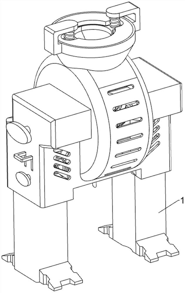
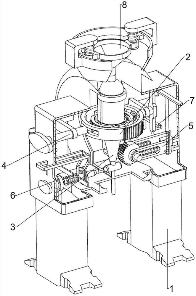
[0036] like figure 1 and figure 2 As shown, an ultra-high molecular weight polyethylene fiber pre-drawing hot water solvent separation device includes a housing 1, a placement mechanism 2, a liquid filling tank 3, a rotating mechanism 4 and a shaking mechanism 5, and the middle position inside the housing 1 is slidingly provided with The liquid filling tank 3 is provided with a placement mechanism 2, the inner wall of the rear side of the casing 1 is provided with a rotating mechanism 4, and the inner wall of the lower right side of the casing 1 is provided with a shaking mechanism 5, and the shaking mechanism 5 and the placement mechanism 2 Cooperate.

[0037] When the solvent needs to be separated, the staff pours the solvent to be separated into the liquid filling tank 3. After completion, the staff closes the bottom of the liquid filling tank 3 by rotating the placement mechanism 2. At this time, the staff rotates the rotating mechanism 4 Make the liquid filling tank 3 ...

Embodiment 2

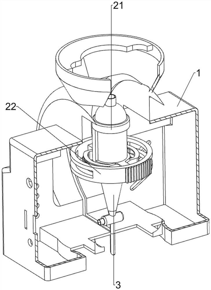
[0039] like figure 2 , image 3 , Figure 4 , Figure 5 , Image 6 , Figure 7 , Figure 8 and Figure 9 As shown, on the basis of Embodiment 1, the placement mechanism 2 includes a first fixed block 21, a first chute plate 22, a rack 23, a first spring 24 and a regulating valve 25, and the outer wall of the liquid filling tank 3 is arranged There is a first fixed block 21, the first fixed block 21 is provided with a first chute plate 22, the front side of the first chute plate 22 is provided with a rack 23, and the left and right sides of the first fixed block 21 are connected with first springs 24, the lower part of the liquid tank 3 is rotatably provided with a regulating valve 25 .

[0040] The rotating mechanism 4 includes a first twisting block 41, a second fixed block 42, a rotating rod 43, a hexagonal sleeve 44 and a connecting ring 45. The right end of the block 41 cooperates with the first spring 24 on the left side. Two second fixed blocks 42 are arranged on ...

Embodiment 3

[0044] like figure 2 , Figure 10 , Figure 11 , Figure 12 , Figure 13 , Figure 14 and Figure 15 As shown, on the basis of Embodiment 2, an opening and closing assembly 6 is also included. The opening and closing assembly 6 includes a second twist block 61, a rotating shaft 62, a stopper 63, a fourth spring 64, a limit rod 65, Limiting groove plate 66 and guide plate 67, the outer wall of shell 1 bottom left side is provided with the second twisting block 61 in rotation, the left side of shell 1 bottom is movably provided with rotating shaft 62, and rotating shaft 62 left ends and second twisting block The inner end of 61 is slidably connected by a coupling, the right end of the rotating shaft 62 cooperates with the regulating valve 25, the right side of the rotating shaft 62 is provided with a stopper 63, the left side of the rotating shaft 62 is wound with a fourth spring 64, and the left side of the second twisting block 61 A limit rod 65 is provided, and a limit...


PUM


Abstract

The invention relates to a separation device, in particular to a separation device for a solvent in ultrahigh-molecular-weight polyethylene fiber pre-drawing hot water. The separation device for the solvent in the ultrahigh-molecular-weight polyethylene fiber pre-drawing hot water in the invention can automatically shake for separation and is high in working efficiency. The separation device comprises: a shell, wherein a liquid containing tank is arranged in the middle of the interior of the shell in a sliding mode; a placing mechanism, which is arranged on the liquid containing tank; a rotating mechanism, which is arranged on the inner wall of one side of the shell; and a shaking mechanism, which is arranged on the inner wall of one side of the lower portion of the shell and is matched with the placing mechanism. The rotating mechanism is rotated to enable the liquid containing tank to rotate downwards by 90 degrees, and after completion of rotation, the shaking mechanism rotates to be matched with the placing mechanism, so the liquid containing tank continuously rotates forwards and backwards to shake and separate the solvent.

Description

technical field [0001] The invention relates to a separation device, in particular to an ultra-high molecular weight polyethylene fiber pre-drawing hot water solvent separation device. Background technique [0002] Ultra-high molecular weight polyethylene fiber, also known as high-strength and high-modulus polyethylene fiber, is currently the fiber with the highest specific strength and specific modulus in the world. It is a fiber spun from polyethylene with a molecular weight of 1 million to 5 million. [0003] In the preparation process of ultra-high molecular weight polyethylene fibers, the solvent needs to be separated. The general separation method is to manually put the solvent in the container, and then separate it by manual shaking. This separation method is laborious. And it takes a lot of time. [0004] Therefore, it is necessary to design a kind of ultra-high molecular weight polyethylene fiber pre-drawing hot water solvent separation device that can automaticall...

Claims


Application Information

Patent Timeline
Patent Type & Authority Applications(China)
IPC IPC(8): B01D17/02B01F11/00
CPCB01D17/0208
Inventor 石崇
Owner 石崇
Why Eureka
Try Eureka