An intelligent automatic loading equipment with material sorting function
A functional and intelligent technology, applied in the stacking of objects, loading/unloading, conveyor objects, etc., can solve the problems of high labor intensity, time-consuming and laborious, and achieve the effect of saving labor.
- Summary
- Abstract
- Description
- Claims
- Application Information
AI Technical Summary
Problems solved by technology
Method used
Image
Examples
Embodiment 1
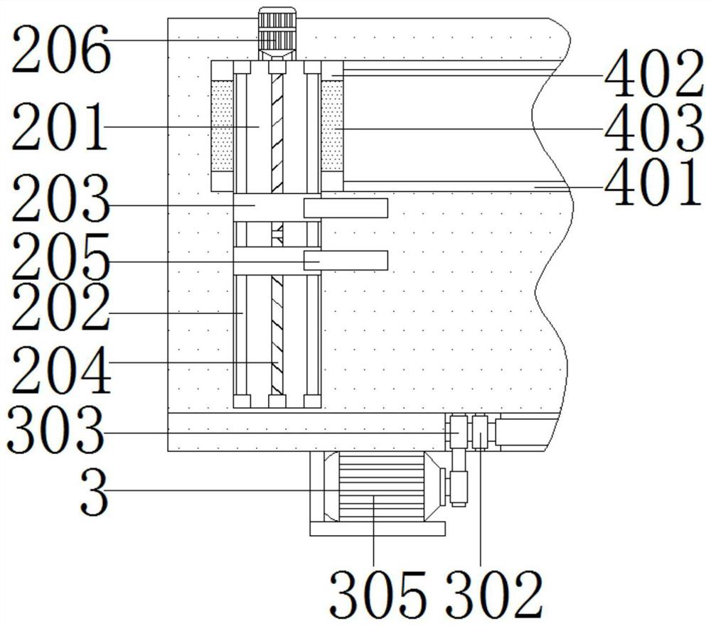
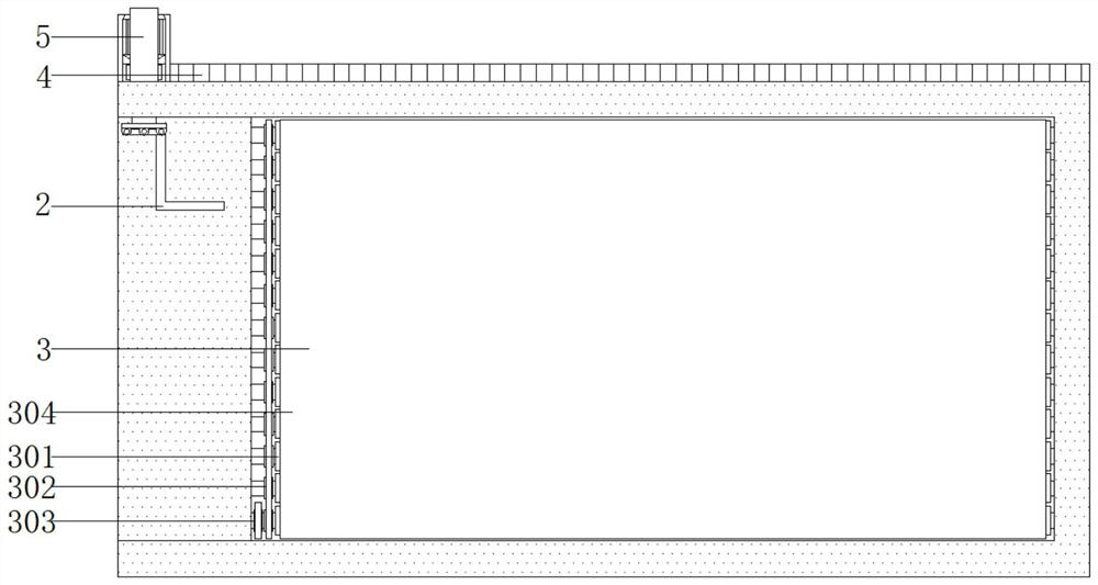
[0035] see Figure 1-5 , an intelligent automatic loading equipment with material sorting function, including a car box 1, a sorting mechanism 2 and a driving mechanism 4, the sorting mechanism 2 is arranged at one end of the car box 1, and the sorting mechanism 2 includes a fixed plate 201, a sliding shaft 202, a moving plate 203, a bidirectional screw rod 204, a bending rod 205 and a first motor 206; a sliding shaft 202 is fixedly installed on both sides of the fixed plate 201, the outer wall of the sliding shaft 202 is slidably sleeved with a moving plate 203, and the middle end of the moving plate 203 is internally threaded A two-way screw 204 is connected, the two-way screw 204 is rotatably connected with the fixed plate 201, and one side of the moving plate 203 is fixedly connected with a bending rod 205; one end of the two-way screw 204 is provided with a first motor 206, the first motor 206 passes through The mounting bracket is fixedly connected to the fixing plate 20...
Embodiment 2
[0038] see Figure 1-5 , the drive mechanism 4 includes a sliding rail 401, a sliding block 402, a sliding plate 403, a gear 404, a third motor 405 and a toothed strip 406; a sliding groove is opened inside one side of the box body 1, and the inner wall of the sliding groove is fixedly connected with the sliding rail 401, A sliding block 402 is slidably connected to the outer wall of the slide rail 401, and a sliding plate 403 is fixedly connected to the outer wall of the sliding block 402; The output end of 5 is fixedly connected to the fixing plate 201 . A gear 404 is rotatably connected to one side of the sliding plate 403, a third motor 405 is fixedly connected to one side of the gear 404, and the third motor 405 is fixedly connected to the sliding plate 403 through a mounting frame; The toothed strips 406 are fixedly connected with the outer wall of one side of the vehicle box 1 .
[0039]Specifically, during use, the third motor 405 is turned on to drive the gear 404 t...
Embodiment 3
[0043] see Figure 1-3 , the bottom of the car box 1 is provided with a conveying mechanism 3, and the conveying mechanism 3 includes a roller 301, a first pulley 302, a second pulley 303, a transmission belt 304 and a second motor 305; One end of the roller 301 is fixedly connected with a first pulley 302, one end of the outermost group of rollers 301 is fixedly connected with a second pulley 303, and a second motor 305 is connected below the second pulley 303 through a belt drive. 305 is fixedly connected to the bottom of the car box 1 . The outer walls of several rollers 301 are provided with transmission belts 304, and several first pulleys 302 are connected by means of belt transmission. The drive belt 304 remains flush with the bottom of the box 1 .
[0044] Specifically, during use, the second motor 305 is turned on to drive the second pulley 303 to rotate, thereby causing the outermost group of rollers 301 to rotate. The plurality of first pulleys 302 are connected ...
PUM
 Abstract
Description
Claims
Application Information
 - R&D
- Intellectual Property
- Life Sciences
- Materials
- Tech Scout
- Unparalleled Data Quality
- Higher Quality Content
- 60% Fewer Hallucinations
Browse by: Latest US Patents, China's latest patents, Technical Efficacy Thesaurus, Application Domain, Technology Topic, Popular Technical Reports.
© 2025 PatSnap. All rights reserved.Legal|Privacy policy|Modern Slavery Act Transparency Statement|Sitemap|About US| Contact US: help@patsnap.com


