Water environment treatment sludge solidification pretreatment device

A pretreatment device and water environment technology, applied in water/sludge/sewage treatment, fixed/solidified sludge treatment, sludge treatment, etc., can solve the problem of reducing the use efficiency of drive motors, easy accumulation of sludge, waste of curing agent, etc. problems, to achieve the effect of reducing equipment freezes, reducing energy consumption, and improving efficiency

Inactive Publication Date: 2021-09-28
中奥生态环境股份有限公司
View PDF7 Cites 0 Cited by
  • Summary
  • Abstract
  • Description
  • Claims
  • Application Information

AI Technical Summary

Problems solved by technology

[0004] This solution solves the problem that silt is easy to accumulate at the bottom of the input box, which makes it inconvenient to clean it. Two drive motors are needed to transport and stir the silt, which reduces the use efficiency of the drive motor and causes waste of energy. , the traditional curing method solidifies the sludge by injecting a curing agent, which wastes a lot of curing agent

Method used


Image

  • Water environment treatment sludge solidification pretreatment device
  • Water environment treatment sludge solidification pretreatment device
  • Water environment treatment sludge solidification pretreatment device

Examples


Embodiment 1

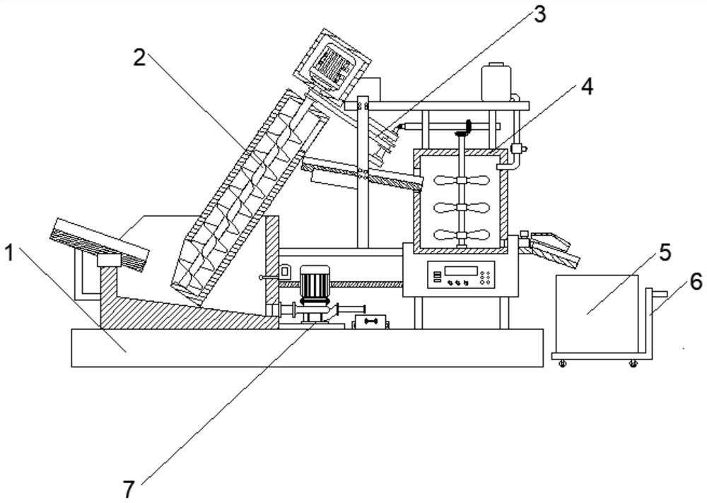
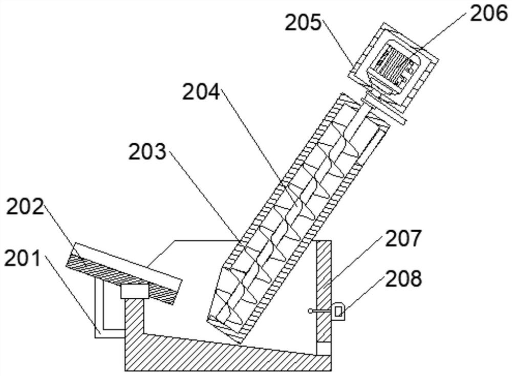
[0030] The above-mentioned input mechanism 2 includes an input box 207 fixedly connected to the bottom plate 1, a side of the input box 207 is provided with a connecting frame 201, and the top end of the connecting frame 201 is fixedly connected with a first guide plate 202, the first guide plate 202 is inclined, and The bottom end of the first guide plate 202 faces the input box 207 , the other side of the input box 207 is provided with a humidity detector 208 , and the input end of the humidity detector 208 penetrates the input box 207 .

[0031] The inner top surface of the above-mentioned input box 207 is provided with an input groove, and a mud guiding pipe 203 is fixedly installed on the groove wall of the input groove. 205, the interior of the installation box 205 is provided with a drive motor 206, the output end of the drive motor 206 runs through the installation box 205 and the mud guide pipe 203 and is fixedly connected with the top of the auger 204, the mud guide p...

Embodiment 2

[0034] The above-mentioned stirring mechanism 4 includes a mounting base 404 fixedly connected to the bottom plate 1, a control box 403 is fixedly installed on the front surface of the mounting base 404, a mixing tank 402 is connected to the top of the mounting base 404, and a stirring tank 402 is provided inside the mixing tank 402. The bottom of the inner wall of the stirring chamber is rotatably connected with a first rotating shaft 406 through a bearing, and several groups of stirring blades 407 are fixedly installed in the middle of the first rotating shaft 406, and a splash prevention mechanism 405 is fixedly installed on one side of the mounting base 404.

[0035] The above-mentioned mixing tank 402 is provided with a support plate 401, one end of the support plate 401 is fixedly installed with a mounting block, the mounting block is fixedly connected with the installation box 205, and the other end of the support plate 401 is fixedly installed with a liquid storage tank ...

Embodiment 3

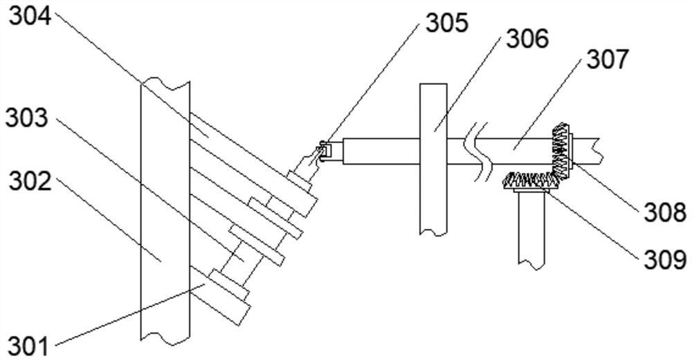
[0039] The above-mentioned transmission mechanism 3 includes a fixed frame 302 fixedly connected with the input box 207 and the mounting seat 404, the top of the fixed frame 302 is fixedly installed with a first limiting plate 301 and a second limiting plate 304, the first limiting plate 301 and the The second limiting plate 304 is all obliquely arranged, the second rotating shaft 303 is arranged between the first limiting plate 301 and the second limiting plate 304, and one end of the second rotating shaft 303 is rotationally connected with the first limiting plate 301 through a bearing, One end of the second rotating shaft 303 and the other end movably pass through the second limiting plate 304 and are movably connected with a universal joint 305 , and the second rotating shaft 303 is connected to the auger 204 through a pulley and a belt transmission.

[0040] The top of above-mentioned mixing bucket 402 is fixedly installed with two installation plates 306, and the top of t...


PUM


Abstract

The invention relates to a water environment treatment sludge solidification pretreatment device which comprises a bottom plate, an input mechanism is arranged on one side of the top face of the bottom plate, a stirring mechanism is arranged on the other side of the top face of the bottom plate, and a transmission mechanism used for being in linkage with the input mechanism and the stirring mechanism is arranged between the input mechanism and the stirring mechanism. A recovery mechanism for recovering the redundant sludge is arranged below the transmission mechanism. The sludge humidity is measured through a humidity detector, a control box can conveniently control the amount of injected curing agents, the use amount of the curing agents can be conveniently reduced, and therefore the sludge curing efficiency is improved; and a driving motor operates to drive an auger to operate, conditions that large amount of manpower is easily consumed during sludge conveying and equipment is blocked are reduced, sludge at the bottom of an input box is sucked in through a sludge inlet pipe and a sludge pump, and the sludge is injected into a recycling box through a sludge outlet pipe, so that recycling efficiency of the sludge is improved, and problem that the sludge at the bottom of the input box is accumulated for long time is solved.

Description

technical field [0001] The invention relates to the field of sludge solidification, in particular to a sludge solidification pretreatment device for water environment control. Background technique [0002] At present, the silt of rivers and lakes is getting deeper and deeper, and it is necessary to dredge the rivers and lakes. The silt is put into the car and taken away, but the silt contains a lot of water and is inconvenient to transport. Therefore, this technology There are flaws and needs to be improved. [0003] During the sludge solidification operation of the sludge solidification equipment on the market, the sludge is easy to accumulate at the bottom of the input box, which makes it inconvenient to clean it. Two drive motors are needed to transport and stir the sludge, which reduces the driving force. The use efficiency of the motor causes a waste of energy. At the same time, the traditional curing method solidifies the sludge by injecting a curing agent, which wast...

Claims


Application Information

Patent Timeline
Patent Type & Authority Applications(China)
IPC IPC(8): C02F11/00B01F7/18B01F15/02G01N33/24
CPCC02F11/008G01N33/24C02F2103/007
Inventor 吴鲁皖马吴艳吴小庆吴腾飞韩坤弟韩伟康铭铭徐胜炜徐胜捷陶国章乔志刚孟祥飞周新宇吴领昌
Owner 中奥生态环境股份有限公司
Why Eureka
Try Eureka