Efficient dust removal and heat preservation type circulating stirring-cage-free grain drying machine

A grain dryer and heat preservation technology, applied in grain drying, non-progressive dryers, dryers, etc., can solve the problems of clogged granaries and blockages, and achieve the effects of avoiding damage, expanding the area, and promoting the effect of tumbling

Active Publication Date: 2021-09-28
ANHUI ZHENGYANG MACHINERY TECH
View PDF8 Cites 0 Cited by
  • Summary
  • Abstract
  • Description
  • Claims
  • Application Information

AI Technical Summary

Problems solved by technology

[0004] Although the overall device can dry and dry the grain, when the grain is introduced into the drying bin through the feed pipe, the dust mixed with the grain will continue to accumulate in the drying bin, and then there will be a problem of blocking the grain bin, so , there is an urgent need for a high-efficiency dust-removing and heat-retaining circulating non-stirring cage grain dryer

Method used


Image

  • Efficient dust removal and heat preservation type circulating stirring-cage-free grain drying machine
  • Efficient dust removal and heat preservation type circulating stirring-cage-free grain drying machine
  • Efficient dust removal and heat preservation type circulating stirring-cage-free grain drying machine

Examples


Embodiment 1

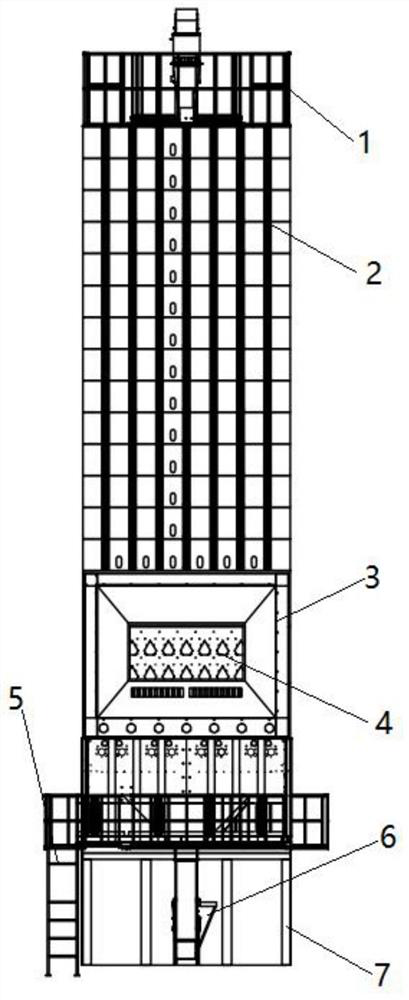
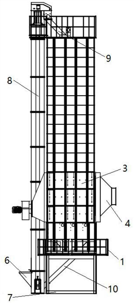
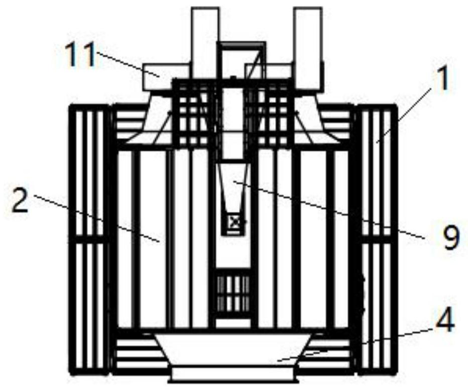
[0033] A high-efficiency dust-removing and heat-retaining circulating non-stirring cage grain dryer, such as Figure 1-5 As shown, it includes a storage bin 2, a drying bin 3 and four pillars 7. The tops of the four pillars 7 are fixed with a hopper 12 through threads, and one side of the outer wall of the hopper 12 is threaded with a second threaded connection. Two guide pipes 10, the top outer wall of the discharge hopper 12 is fixed with a mounting plate by bolts, and the surrounding outer walls of the mounting plate are fixed with brackets 1 by bolts, and the top outer wall of the mounting plate is connected with the bottom of the drying bin 3 by bolts. The top outer wall of the drying bin 3 is connected with the bottom of the grain storage bin 2 by bolts, the outer walls on one side of the four pillars 7 are fixed with a hoist 8 by bolts, and the outer walls on both sides of the hoist 8 are connected with a fixed frame 11 by bolts, and One side of the outer wall of the fi...

Embodiment 2

[0041] A high-efficiency dust-removing and heat-retaining circulating non-stirring cage grain dryer, such as Figure 6 As shown, in order to avoid the problem of side leakage when grain passes through the guide hole 19; this embodiment makes the following improvements on the basis of embodiment 1: the outer wall of the top of the drying box 23 is screwed with a snap ring 28, And the top of snap ring 28 is welded with arc-shaped convex plate 29, and the joints of snap-fit ​​ring 28, arc-shaped convex plate 29 and drying box 23 have the same feeding hole respectively, and the outer walls of both sides of drying box 23 A filter screen 27 is provided respectively, a guide hole 31 is opened on the bottom outer wall of the drying box 23, a material trough 30 is arranged inside the drying box 23, and the internal structure of the drying box 23 is an arc-shaped surface structure.

[0042] When the arc-shaped convex plate 29 rotates to the bottom of the guide hole 19, the arc-shaped co...


PUM


Abstract

The invention discloses an efficient dust removal and heat preservation type circulating stirring-cage-free grain drying machine, and relates to the technical field of stirring-cage-free grain drying machines. The problem of dust driving during drying is solved. The efficient dust removal and heat preservation type circulating stirring-cage-free grain drying machine specifically comprises a grain storage bin, a drying bin and four supporting columns, a discharging hopper is arranged at the tops of the four supporting columns, a second flow guide pipe is in threaded connection with the outer wall of one side of the discharging hopper, a mounting plate is arranged on the outer wall of the top of the discharging hopper, supports are arranged on the outer wall of the periphery of the mounting plate, a lifting machine is arranged on the outer walls of one sides of the four supporting columns, fixing frames are arranged on the outer walls of the two sides of the lifting machine, the outer walls of one sides of the fixing frames are connected with the periphery of the top of the grain storage bin through supports, a first flow guide pipe is arranged on the top of the grain storage bin, a stirring-free material mixing mechanism is arranged in the drying bin, and four heating rings are fixed to the two sides of the bottom of the drying bin through supporting plates respectively. The problem that grains are damaged and become brown rice is avoided, and the grain drying efficiency is improved.

Description

technical field [0001] The invention relates to the technical field of a non-stirring cage grain dryer, in particular to a high-efficiency dust removal and heat preservation type circulation non-stirring cage grain dryer. Background technique [0002] When drying grain with a dryer in the grain production process, it needs to go through multiple cycles. However, the traditional dryer needs to be transported through two augers for each cycle. The grain is squeezed by the auger blades when it is conveyed by the auger, and it is easy to break the shell, forming brown rice, and it is squeezed multiple times in multiple cycles, and the grain is easily broken. At the same time, because the grain is squeezed against each other when it is conveyed inside the auger, the auger is also easy to wear, causing the grain to block and damage the motor of the auger, and the speed of the auger cannot be set too fast when conveying, and the drying time is relatively long, resulting in The pro...

Claims


Application Information

Patent Timeline
Patent Type & Authority Applications(China)
IPC IPC(8): F26B11/12F26B23/06F26B25/00F26B25/02F26B25/04
CPCF26B11/12F26B23/06F26B25/002F26B25/02F26B25/04F26B2200/06
Inventor 张为法罗会强许为青胡家冀宁传烨李盛婷
Owner ANHUI ZHENGYANG MACHINERY TECH
Why Eureka
Try Eureka